background image


00-02-0271 


2018-10-23 


Section 50


Series S1501 Selectronic

®


Micro-Controller/Annunciator 

Model Year 2011 and Earlier 

Installation and Operations Manual 

Содержание Selectronic S1501 series

Страница 1: ...00 02 0271 2018 10 23 Section 50 SeriesS1501Selectronic Micro Controller Annunciator Model Year 2011 and Earlier Installation and Operations Manual...

Страница 2: ...mation before installing BEFORE BEGINNING INSTALLATION OF THIS FW MURPHY PRODUCT Read and follow all installation instructions A visual inspection of this product before installation for any damage du...

Страница 3: ...6 S1501 System Typical Hook Up 7 Power Supply Typical Wiring Diagram 11 Operation 12 Operating the S1501 Interface 12 Sequence of Operations Engine Mode 13 Sequence of Operations Motor Mode 15 System...

Страница 4: ...THIS PAGE INTENTIONALLY LEFT BLANK...

Страница 5: ...r an alphanumeric display and keypad for operator access to field adjustable functions and a communication port RS232 or RS485 Modbus RTU slave This port allows for remote control functions such as St...

Страница 6: ...the power supply end and has a 15 pin D sub connector on the S1501 Head end Sensor Inputs User selectable Sensor Input types Shutdown or Alarm Only are available for each sensor The sensor inputs are...

Страница 7: ...NOTE For tachometer sensing a magnetic pickup is recommended Built In Barrier within the Power Supply The S1501 power supply circuit is isolated from the Head by the intrinsically safe barrier locate...

Страница 8: ...oof enclosure It is intended for mounting in a flat panel First cut a square mounting hole of 3 5 8 in 92 mm x 3 5 8 in 92 mm Insert the Head from the front side of the panel and install the two mount...

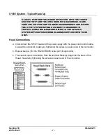
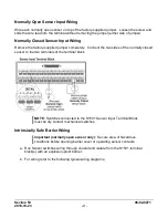
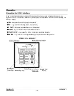
Страница 9: ...Section 50 00 02 0271 2018 10 23 5...

Страница 10: ...ATION REQUIREMENTS THE S1501 COMPLETE SYSTEM MUST BE INSTALLED IN ACCORDANCE WITH THE NATIONAL ELECTRICAL CODE NEC CLASS I DIVISION 1 GROUP D ARTICLE 504 SPECIFICATIONS SENSOR INPUT WIRES MUST BE SEPA...

Страница 11: ...AMAGE REFER TO THE SPECIFIC SYSTEM APPLICATION WIRING DIAGRAM SUPPLIED WITH YOUR UNIT Head Connections a Interconnect the S1501 head and the power supply with the power and control cable secure the co...

Страница 12: ...seal in the conduit within 18 in 457 mm of Power Supply enclosure seal unused conduit holes Important Green screw above conduit hole power supply is to attach equipment ground per NEC b Customer Inst...

Страница 13: ...the two sides of the normally closed sensor to the two terminals of the terminal block NOTE Switches connected to the S1501 Sensor Input Terminal Block must be dry contact mechanical switches Intrinsi...

Страница 14: ...10 Normally Open System Barrier LCDT ISB barrier optional Normally Closed System Barrier For normally closed non intrinsically safe sensors use an approved intrinsically safe barrier and wire accordin...

Страница 15: ...wires from damage Refer to the specific system application wiring diagram supplied with your unit NOTE 1 K 1 thru K 7 are relay outputs form C dry contacts D1 thru D8 are LED indicators D1 POWER ON D...

Страница 16: ...Tachometer calibration Overspeed Underspeed Run Hourmeter ETM and Sensor Setup YES key used for scrolling up increment NO key used for scrolling down decrement RESET key used to reset alarms or shutd...

Страница 17: ...to zero Unit advances to Crank cycle LUBE CYCLE Prelube 00 On Off Off Off Off On On CRANK CYCLE Crank Relay energizes If the Run Delay Preset is 0 the controller will wait for a Crank RPM permissive t...

Страница 18: ...rm relay is picked up Unit continues to scans for fault or stop condition Speed xxxxrpm ETM xxxxx x hrs Off Off On On On On On FAULT SHUTDOWN Unit receives a fault at sensor 4 for instance The Fuel Va...

Страница 19: ...Signal not received before the delay expires Fault occurs All relays de energize Motor Starter Failure Off Off Off Off Off Off Off S1501 Reset key pressed Unit waiting on start input Waiting On Start...

Страница 20: ...Off Off Off Off Off Off S1501 Mode key pressed Shutdown type displayed Sensor Input 04 Class B1 Shutdown Off Off Off Off Off Off Off S1501 Reset key pressed Unit waiting on start input Waiting On Star...

Страница 21: ...cted screens The following Set Ups are available only under ADVANCED SETUP mode Tach Crank Set Up This set up screen allows you to calibrate the internal tachometer with pulses per revolution and set...

Страница 22: ...r ungrounded NO system If the Permissive input is not satisfied when the timer expires a Permissive Failure fault shutdown will occur NOTE Terminal 32 is dedicated for the Permissive Pressure Input To...

Страница 23: ...a warmup time Process x xx This timer locks out sensor inputs configured as class P after energizing the Load relay This is typically used for Process alarms and shutdowns which do not clear until the...

Страница 24: ...P PASSWORD ERROR User will again be prompted to enter correct password After 3 unsuccessful entries the Advanced Set up is aborted and screen will return to Waiting On Start ADVANCED SETUP Pulses rev...

Страница 25: ...s the low speed RPM at which the S1501 signals an internal Underspeed Shutdown This is not armed until the Class B1 timer expires ETM 1k Hr xx Preset the Elapsed Time Hours thousands hours or use the...

Страница 26: ...NO keys to scroll through available characters Press MODE to move forward on character or RESET to move backward When the shutdown modification is completed press ENTER to save the new message The Se...

Страница 27: ...Remote Stop is seen Remote Start Stop Jumper installed in TB31 A valid sequence occurs when a Remote Start signal is seen Likewise a valid stop occurs when the Remote Stop signal is seen Maintain Star...

Страница 28: ...17 Bit 1 TB18 etc 40008 Read Inputs TB33 48 Status bitmapped Bit 0 TB33 Bit 1 TB34 etc 40009 Read Inputs TB49 64 Status bitmapped Bit 0 TB49 Bit 1 TB50 etc 40010 Read Write Start Stop Register writabl...

Страница 29: ...fuse within the S1501 power supply and replace if necessary NOTE If after all of the above has been done and there is still no display return the S1501 to Murphy for repair or replacement Symptom Engi...

Страница 30: ...1 2018 10 23 26 Check sensor wires with an ohmmeter and meg or high potential test only with wires disconnected from sensor terminal block NOTE If shutdowns still result contact your nearest Murphy re...

Страница 31: ...Lockout Class B2 Lockout Process Lockout Idle Cooldown Ignition Ground Postlube Cooler Sensor Inputs Terminal Block Rail mount DIN type 32 terminals screw type Opto Isolated Tach Run Input Magnetic pi...

Страница 32: ...rogram RS232 RS485 port 64 sensors Terminal Block only Ribbon Cable Assembly 120 VAC 12 or 24 VDC Power Supply Power and Control Cable Assembly 72 in 1 8 m long Power Supply with 90 Conduit Elbow fitt...

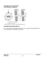
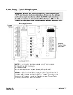
Страница 33: ...Section 50 00 02 0271 2018 10 23 29...

Страница 34: ......

Отзывы: