


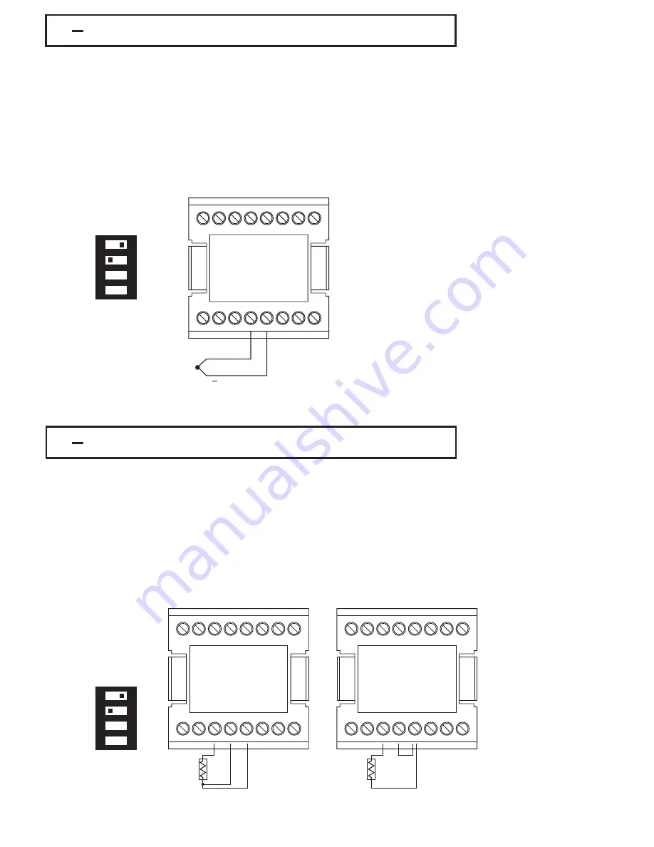
2 6 Thermocouple Input Wiring
2 6 Thermocouple Input Wiring
1
9
2
10
3
11
4
12
5
13
6
14
7
15
8
16
+
Figure 2.5
Thermocouple Input Wiring
Figure 2.5
Thermocouple Input Wiring
1
2
3
4
ON
DIP Switch
DIP Switch
If the length of thermocouple plus the extension wire is too long, it may affect the
temperature measurement. A 400 ohms K type or a 500 ohms J type thermocouple
lead resistance will produce 1 degree C temperature error approximately.
If the length of thermocouple plus the extension wire is too long, it may affect the
temperature measurement. A 400 ohms K type or a 500 ohms J type thermocouple
lead resistance will produce 1 degree C temperature error approximately.
2 7 RTD Input Wiring
2 7 RTD Input Wiring
Figure 2.6
RTD Input Wiring
Figure 2.6
RTD Input Wiring
1
2
3
4
ON
DIP Switch
DIP Switch
Two-wire RTD should be avoided, if possible, for the purpose of accuracy. A
0 . 4 o h m l e a d r e s i s t a n c e o f a t w o -w i r e R T D w i l l p r o d u c e 1 d e g r e e C
temperature error.
Two-wire RTD should be avoided, if possible, for the purpose of accuracy. A
0 . 4 o h m l e a d r e s i s t a n c e o f a t w o -w i r e R T D w i l l p r o d u c e 1 d e g r e e C
temperature error.
1
9
2
10
3
11
4
12
5
13
6
14
7
15
8
16
RTD
Three-wire RTD
Three-wire RTD
1
9
2
10
3
11
4
12
5
13
6
14
7
15
8
16
RTD
Two-wire RTD
Two-wire RTD
RTD connection are shown in Figure 2.6, with the compensating lead connected
to
terminal 12. For two-wire RTD inputs, terminals 12 and 13 should be linked. The
three-wire RTD offers the capability of lead resistance compensation provided that
RTD connection are shown in Figure 2.6, with the compensating lead connected
to
terminal 12. For two-wire RTD inputs, terminals 12 and 13 should be linked. The
three-wire RTD offers the capability of lead resistance compensation provided that
UM9300 2.0
UM9300 2.0
18
IThermocouple input connections are shown in Figure 2.5. The correct type of
thermocouple extension lead-wire MUST be used for the entire distance from
thermocouple sensor to connection to the controller. Splices and joints should be
avoided if at all possible. POLARITY MUST be obser ved when connecting
thermocouples.


