


UM9090Rev1
4
6. INSTALLATION
6. INSTALLATION
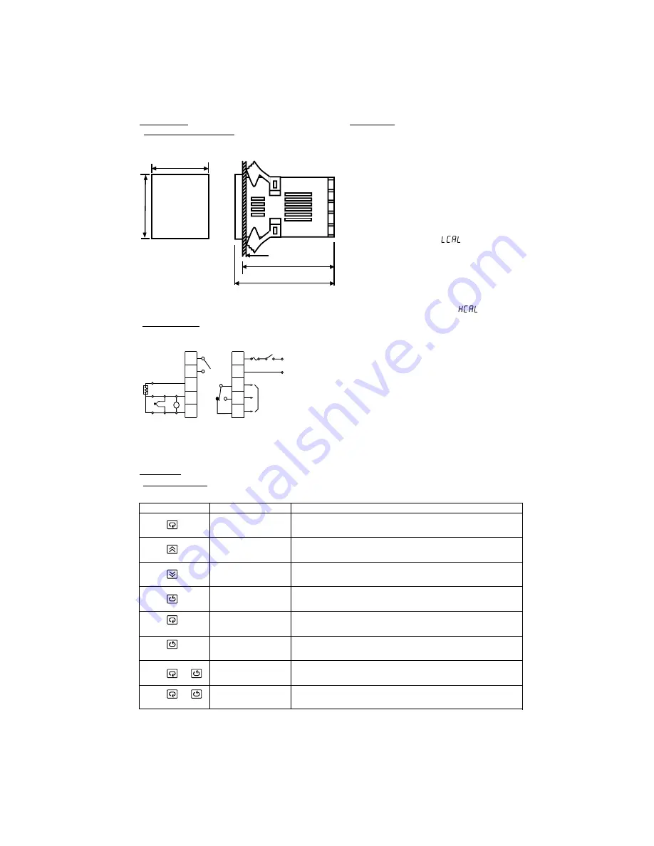
6.1 DIMENSIONS & PANEL CUTOUT
6.1 DIMENSIONS & PANEL CUTOUT
Panel
(45 mm)
Figure 6.1 Mounting Dimensions
TOUCHKEYS
FUNCTION
DESCRIPTION
Scroll Key
Long Scroll
Press
for 6 seconds
Press
and
Up Key
Down Key
Return Key
Long Return
Output Percentage
Monitor
Manual Mode
Execution
* F1: Fuse, S1: Power Switch
6.2 WIRING DIAGRAM
6.2 WIRING DIAGRAM
8. OPERATION
8. OPERATION
8.1 KEYPAD OPERATION
8.1 KEYPAD OPERATION
Press
for 6 seconds
Press
and
for 6 seconds
Increases the parameter
Advance the index display to the desired position.
Index advanced continuously and cyclically by pressing this keypad.
Decreases the parameter
Resets the controller to its normal status. Also stops auto-tuning,
output percentage monitoring and manual mode operation.
Allows more parameters to be inspected or changed.
1. Executes auto-tuning function
2. Calibrates control when in calibration level
Allows the set point display to indicate the control output value.
Allows the controller to enter the manual mode.
7. CALIBRATION
7. CALIBRATION
FDC-9090
1
2
3
4
5
6
7
8
9
10
+
+
+
_
_
_
Alarm
Com.
Alarm
N/O
V
Control Output 1
F1 S1
90 - 264 VAC,50/60HZ
RTD
* With power on, it has to wait for 12 seconds to memorize the new values of parameters once it been changed.
Note: Do not proceed through this section unless their is a
genuine need to re-calibrate the controller. All previous
calibration date will be lost. Do not attempt re-calibration
unless you have available appropriate calibration equipment.
If calibration data is lost, you will need to return the controller
to your supplier who may apply a charge for re-calibration.
Prior to calibration ensure that all parameter settings are
correct (input type, C / F, resolution, low range, high range).
B
B
1. Remove sensor input wiring and connect a standard input
simulator of the correct type to the controller input. Verify
correct polarity. Set simulated signal to coincide with low
process signal (e.g. zero degrees).
2. Use the Scroll Key until the "
" appears on the PV
Display. (Refer to 8.2)
3. Use the Up and Down Keys until the SV Display
represents the simulated input.
4. Press the Return Key for at least 6 seconds(maximum 16
seconds), then release. This enters the low calibration
figure into the controller's non-volatile memory.
5. Press and release the Scroll Key. "
" appears on
the PV Display. This indicates the high calibration point.
6. Increase the simulated input signal to coincide with high
11 process signal (e.g. 100 degrees).
7. Use the Up and Down Keys until the SV Display
represents the simulated high input.
8. Press the Return Key for at least 6 seconds (maximum 16
seconds), then release. This enters the high calibration
figure into the controller's non-volatile memory.
9. Turn power off the unit, remove all test wiring and replace
sensor wiring (observing polarity).
1.77 “
1.77
“
(45
m
m
)
94 mm
3.70 “
86 mm
3.38 “


