13
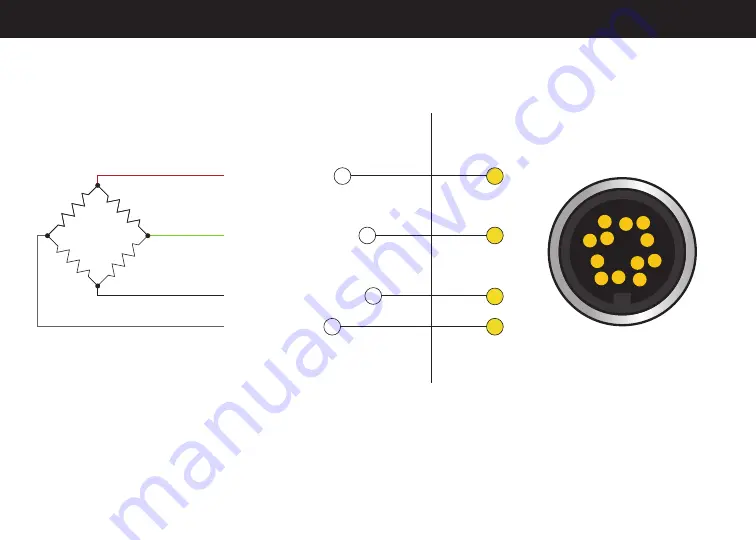
LSB200 TO USB520 WIRING
USB520
G
M
F E
D
C
L
B
A
K
J
H
mV/V Wiring Example
Bridge Sensor
XXX
Ω
+ Excitation
(Red) Pin
+ Signal
(Green/Yellow) Pin
– Signal
(White) Pin
– Excitation
(Black/Blue) Pin
1
2
4
3
A
B
C
D
Note:
For sensors with ± Sense, the sense wires must be connected to
± Excitation or clipped off.


