background image

103

<Functions of Linkage Menu>

● Select the function name 

and return to the Linkage 

menu  by  touching  the


R T N

  b u t t o n .


O r   t h e


H O M E / E X I T

  b u t t o n   i s 

pushed.

<SensorTouch™>

RETURN

● Call page 7 by touching the S1 button 6 times from 

the [SENSOR] menu.

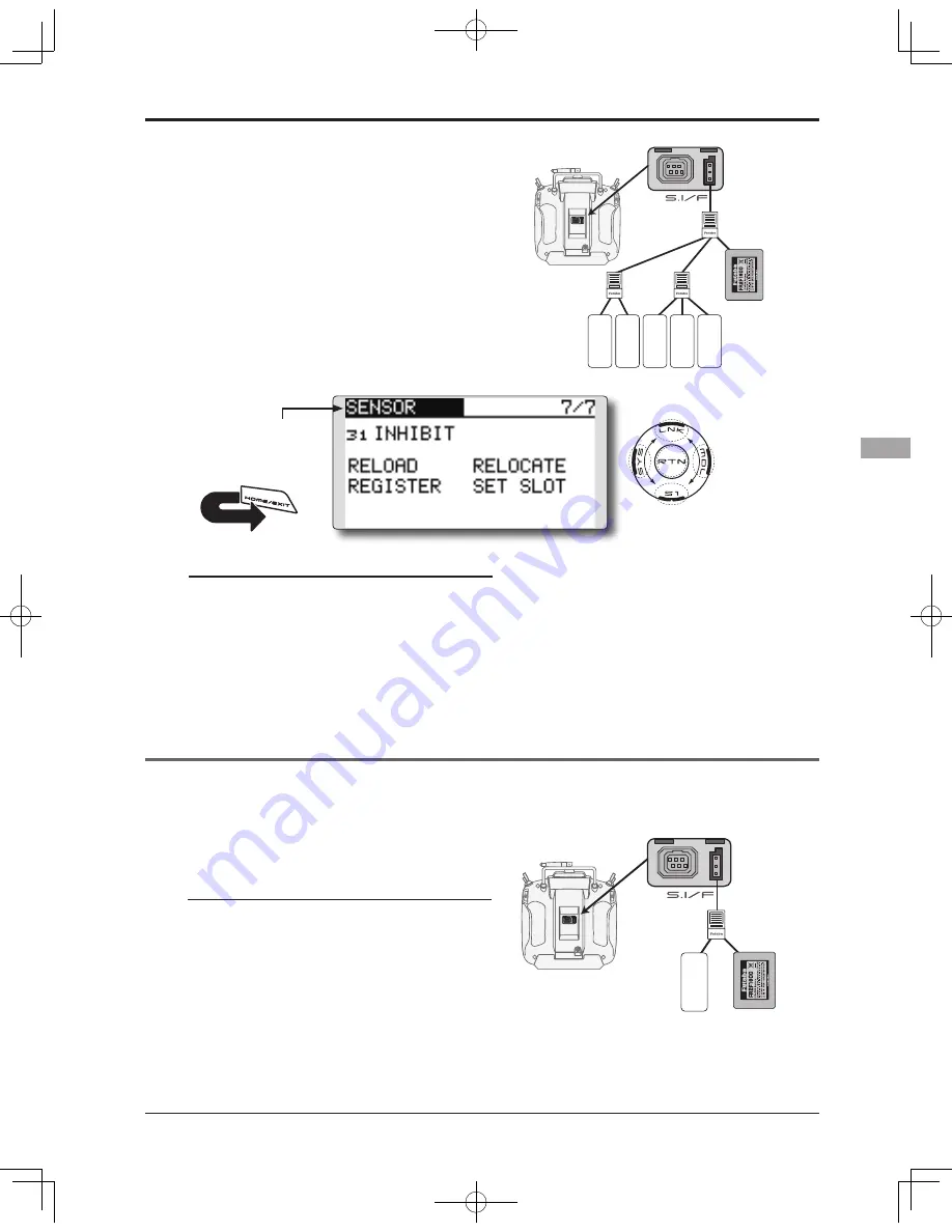
SENSOR : RELOAD

SENSOR : REGISTER

This page is set when using multiple telemetry sensors of the same type.

This page is set when using multiple telemetry sensors of the same type.

When using multiple sensors of the same type 

the sensors must be registered in the transmitter. 

Connect all the sensors to be used to the T14SG as 

shown in the figure at the right and register them by 

the following procedure. The ID of each sensor is 

registered in the transmitter.

This function registers an additional sensor. 

Connect the sensor as shown in the figure at the 

right and register it by the following procedure. 

The sensor ID is registered in the transmitter.

All the sensors to be used are connected. 

SENSOR

SENSOR

3-way hub 

or Y-harnesses

Receivers

Battery

T14SG

SENSOR

SENSOR

SENSOR

3-way hub 

or Y-harnesses

Receivers

Battery

T14SG

SENSOR

Reading all the sensors to be used

1.  Connect  all  the  sensors  and  receiver 

batteries to be used to the T14SG through a 

hub as shown in the figure above.

2. Move the cursor to “RELORD” on page 7 of 

the [SENSOR] screen.

3. Touch the RTN button.
   All the sensors are registered and can be 

used.

Additional sensor registration

1. Connect the sensor and receiver battery 

to be used to the T14SG through a hub as 

shown in the figure at the right.

2. Move the cursor to “REGISTER” on page 7 of 

the <Sensor> screen.

3. Touch the RTN button.
    The sensor is registered and can be used.

*

When  the  number  of  slots  needed  in  registration  is 

insufficient, an error is displayed and registration cannot be 

performed. Disable unused slots or perform the following 

relocate.

Содержание 14SG S.Bus2

Страница 1: ...1M23N27902 14 CHANNEL COMPUTER SYSTEM TM TM ...

Страница 2: ...metry System 32 BASIC OPERATION 33 Battery Charging 33 How to charge the NiMH Battery 33 How to turn ON OFF the transmitter 34 When turning on 34 When turning off 34 Low battery alarm and auto shut down 34 Warning display at power on 34 Registration of the user s name 34 Home screen 35 User Menu 36 Link procedure T14SG R7008SB 37 Range testing your R C system 39 RACEIVER AND SERVO INSTALLATION 40 ...

Страница 3: ...le Curve Air only 118 THR Delay Air only 119 AIL Differential Except 1 AIL 120 Flap Setting 2 FLP and up 121 AIL to Camber FLP 2 AIL 2 FLP and up 122 AIL to Brake FLP Glid only 4 FLP 123 AIL to RUD 124 RUD to AIL 125 Camber Mix Except 1 AIL 127 ELE to Camber Except 1 AIL 129 Camber FLPto ELE 2 AIL 1 FLPand up 130 Butterfly Glid only normal wing 2 AIL and up flying wing 2 AIL 1FLP and up 131 Trim M...

Страница 4: ...and US manual corrections will be available on this web page If you do not find the answers to your questions there please see the end of our F A Q area for information on contacting us via email for the most rapid and convenient response Don t have Internet access Internet access is available at no charge at most public libraries schools and other public resources We find internet support to be a...

Страница 5: ...t and replacement of parts on this product Any such changes may void the warranty Compliance Information Statement for U S A This device trade name Futaba Corporation of America model number R7008SB complies with part 15 of the FCC Rules Operation is subject to the following two conditions 1 This device may not cause harmful interference and 2 This device must accept any interference received incl...

Страница 6: ...ion To comply with FCC RF exposure compliance requirements a separation distance of at least 20cm must be maintained between the antenna of this device and all persons This device must not be co located or operating in conjunction with any other antenna or transmitter Meaning of Special Markings Pay special attention to safety where indicated by the following marks DANGER Procedures which may lead...

Страница 7: ...rplane flying field You can find model clubs and fields by asking your nearest hobby dealer or in the US by contacting the Academy of Model Aeronautics You can also contact the national Academy of Model Aeronautics AMA which has more than 2 500 chartered clubs across the country Through any one of them instructor training programs and insured newcomer training are available Contact the AMA at the ...

Страница 8: ...t allow NiMH NiCd cells to overheat at any time Cells which reach greater than 140 degrees Fahrenheit 60 C should be placed in a fireproof location NiMH NiCd cells will not charge fully when too cold or show full charge It is normal for the batteries to become warm during charging but if the charger or battery becomes excessively hot disconnect the battery from the charger immediately Always inspe...

Страница 9: ...pectedly turn on and cause a severe injury While you are getting ready to fly if you place your transmitter on the ground be sure that the wind won t tip it over If it is knocked over the throttle stick may be accidentally moved causing the engine to speed up Also damage to your transmitter may occur In order to maintain complete control of your aircraft it is important that it remains visible at ...

Страница 10: ...ype are set in advance at the factory Data input Large graphic LCD and new type Touch Sensor substantially improve ease of setup Stick Improved feel adjustable length and tension Ni MH battery T14SG is operated by a 6 0 V 1 800 mAh Nickel Metal Hydride battery SD card Secure Digital memory card Not included Model data can be saved to an SD card SD 32MB 2GB SDHC 4GB 32GB When T14SG transmitter soft...

Страница 11: ...nel FASSTest 2 4G system Transmitting frequency 2 4GHz band System FASSTest14CH FASSTest12CH FASST MULT FASST 7CH S FHSS switchable Power supply 6 0V HT5F1800B NiMH battery Receiver R7008SB FASSTest 2 4G system dual antenna diversity S BUS system Power requirement 3 7V 7 4V battery or regulated output from ESC etc 1 Size 0 98 x 1 86 x 0 56 in 24 9 x 47 3 x 14 3 mm Weight 0 38 oz 10 9g 1 When using...

Страница 12: ...nsor please purchase an optional sensor in order to utilize bidirectional communication system and to acquire the information from a model high up in the sky Temperature sensor SBS 01T Altitude sensor SBS 01A RPM sensor magnet type SBS 01RM RPM sensor optical type SBS 01RO GPS sensor SBS 01G Voltage sensor SBS 01V Neckstrap a neckstrap may be connected to your T14SG system to make it easier to han...

Страница 13: ... SG SH Switch SA SB SE SF Slide Lever LS Slide Lever RS Digital Trim T3 T4 Power Switch Volume LD RD Stick Stick Digital Trim T1 T2 U MENU MON User Menu Servo Monitor Button HOME EXIT Button It slides upwards and turns on SensorTouchTM SYS LNK MDL RTN S1 J1 J2 J4 J3 Transmitter controls ...

Страница 14: ...e transmitter is displayed by LED at the bottom left and right sides of the T14SG logo Rotating antenna The antenna can be rotated 90 degrees and angled 90 degrees Forcing the antenna further than this can damage it The antenna is not removable 90 90 Caution Please do not grasp the transmitter s antenna during flight Doing so may degrade the quality of the RF transmission to the model Do not carry...

Страница 15: ...tion You can use each setting screen of the mixing functions to select volumes and define the direction of a movement Digital Trim T1 T2 T3 T4 Digital Trim T1 T2 T3 and T4 This transmitter is equipped with four 4 digital trims Each time you press a trim button the trim position moves one step If you continue pressing it the trim position starts to move faster In addition when the trim position ret...

Страница 16: ...nsor Movement of cursor value input or mode selection Movement of the cursor on the menu screen and movement of the cursor among items on a setup screen can be controlled by scrolling your finger to the left and right in the direction of the arrow in the scrolling diagram above You can also go to the next page if there is a next page This scrolling technique is also used for data input value input...

Страница 17: ...smitter to a location away from the noise source Stick Adjustment Adjustment of the stick lever length You can adjust the length of stick levers as you like It is recommended to adjust the length of the sticks in line with your hand size 1 Hold the lever head B and turn the lever head A counter clockwise The lock will be released 2 Turn the lever head A clockwise as you hold the lever head B after...

Страница 18: ...u loosen the screw too much it can interfere with the operation of the sticks internally The stick can be adjusted to how quickly it returns to neutral screw is clockwise Stick tension maximum Stick tension minimum screw is counter clockwise A screw is kept from coming out from a line A screw is kept from coming out from a line The screw will touch the case The screw will touch the case Stick Tens...

Страница 19: ...ard is a precision device do not use excessive force when inserting Restrictions when using an SD card The following restrictions apply when using an SD card The SD card must first be initialized using the T14SG dedicated format The SD card cannot be used as is without formatting to the T14SG Initializing destroys all the data previously saved on the card An SD card formatted to the T14SG cannot b...

Страница 20: ...r to FORMAT and touch the RTN button To cancel formatting move the cursor to CANCEL and touch the RTN button 4 Move the cursor to YES and touch the RTN button Formatting starts During formatting the NOW FORMATTING message is displayed When formatting is completed The FORMAT COMPLETED message is displayed Depending on the card capacity and speed formatting may take as long as several minutes IMPORT...

Страница 21: ...sses Earphone plug It is not used now The function after upgrade Warning Do not connect any other chargers except the special charger to this charging connector If you take out the NiMH battery HT5F1800B from the transmitter you can use the optional quick charger CR 2000 corresponding to NiMH battery Trainer Connector S BUS S I F Connector Earphone Plug Connector for battery charger This is the co...

Страница 22: ...release tab and pull the battery downwards to remove 4 Close the battery cover completely Warning Be careful not to drop the battery Never disconnect the battery connector from the T14SG transmitter after turning off the power until the screen is completely blank and the transmitter has shut down completely Internal devices such as memories may be damaged If there is any problem the message Backup...

Страница 23: ...rge from the charger only for LiFe Warning Follow the manual of a LiFe battery Don t charge the LiFe battery with the NiMH charger of 14SG attachment Be sure to remove from T14SG and to charge with the charger only for LiFe Be sure to change the voltage of LOW BATTERY WARNING into 6 0V from 5 6V LiFe SPACER LiFe Battery The balance charge connector is not connected in the state where the battery i...

Страница 24: ...els and power 8 SB outputs of 8 channels or S BUS port S BUS Servo S BUS Gyro When using 8 SB as S BUS you have to set CH MODE of the following page to mode B or mode D S BUS2 outputs of S BUS2 port S BUS2 Servo S BUS2 Gyro Telemetry Sensor When using 9 or more channels use an S BUS function or use a second R7008SB and link both to your transmitter Connector insertion Firmly insert the connector i...

Страница 25: ...ibed by the chart below 4 Each press of the Mode Link button advances the receiver to the next mode 5 When you reach the mode that you wish to operate in press and hold the Mode Link button for more than 2 seconds 6 Once locked into the correct mode the LED will change to a solid color 7 Please cycle the receiver s power off and back on again after changing the Channel Mode Receiver connector Sett...

Страница 26: ... signal condition is obtained at any flying attitude 3 The antennas must be kept away from conductive materials such as metal carbon and fuel tank by at least a half inch The coaxial part of the antennas does not need to follow these guidelines but do not bend it in a tight radius 4 Keep the antennas away from the motor ESC and other noise sources as much as possible The two antennas should be pla...

Страница 27: ... the deepest point How to protect the receiver from vibration and water Wrap the receiver with something soft such as foam rubber to avoid vibration If there is a chance of getting wet put the receiver in a waterproof bag or balloon to avoid water Receiver s antenna Never cut the receiver s antenna Do not bind the receiver s antenna with the cables for servos Locate the receiver s antenna as far a...

Страница 28: ...S S BUS2 special settings and mixes in your transmitter may be unnecessary The S BUS S BUS2 servos memorize the number of channels themselves Settable with the T14SG The S BUS S BUS2 system and conventional system receiver conventional CH used can be mixed Receiver R7008SB Battery FR2F1800 Optional Switch HSW L Throttle servo BLS173SV Optional Aileron servo BLS174SV 2 Optional Elevator servo BLS17...

Страница 29: ...ply used When a large number of servos are used or when high current servos are used the servos can be driven by a separate power supply by using a separate Power Supply 3 way Hub Terminal box Four connectors can be inserted Three connectors can be inserted Used when using a separate power supply battery S BUS Port 8 SB Orange Green When using 8 SB as S BUS you must set the receiver to Mode B or M...

Страница 30: ...ector S BUS2 Port S BUS Port 8 SB Hub Hub Hub Hub Rudder Servo S BUS2 Servo S BUS Servo S BUS2 servo Connection is possible S BUS2 gyro Connection is possible S BUS servo Connection is impossible Telemetry sensor Connection is impossible S BUS2 GYRO CH Mode is set to ModeB D Telemetry Sensor S BUS servos and gyros and S BUS2 servos and gyros must be used in the correct receiver ports Please refer ...

Страница 31: ...BUS S BUS2 device Telemetry sensor Receivers Battery T14SG 1 Connect the S BUS device and battery you want to set with a 3 way hub or Y harnesses as shown in the figure 2 Turn on the transmitter power 3 Call the setup screen Servo System Menu S BUS Servo Sensor Linkage Menu Sensor 4 Perform setting in accordance with each screen 5 This sets the channel and other data for each S BUS servo or teleme...

Страница 32: ...it is linked to S BUS2 Connector Temperature Sensor Slot 1 Slot 2 Slot 3 5 Slot 6 Slot 7 Slot 8 15 Slot 16 Receiver Battery voltage is displayed at the transmitter Drive battery voltage is displayed at the transmitter Switch T14SG Terminal box HUB HUB HUB Info Info Info Info Info voltage Signal RPM Sensor Altitude Sensor Voltage Sensor GPS Sensor Slot 17 Sensor Sensor Sensor Telemetry sensor sold ...

Страница 33: ...the charging indicator LED lamp is on Turn off the transmitter while charging the battery 3 Remove the battery after 15 hours Battery charging will not automatically stop Remove the battery and transmitter from the charger and remove the charger from the wall socket It is recommended to reactivate the battery by cycling several times if the battery has not been used for a long period In the case o...

Страница 34: ...d Warning display at power ON Airplane Helicopter When the throttle stick during Power On is at the high side or over 1 3 stick a warning will be displayed below 1 3 stick the warning display goes off Registration of the user s name If so desired the T14SG transmitter can indicate the owner s name User s name setup screen 1 Turn on the power of the transmitter The home screen appears 2 Lightly tou...

Страница 35: ...tton The setting screen appears RF indicator Battery Indicator When the battery voltage reaches 5 2V Change in Warning Menu the alarm will beep Land your aircraft immediately System mode System FASSTest14CH etc mode is displayed here Use the cursor to highlight this then touch the RTN button to call the frequency set up screen 2nd Home screen Touch the RTN button at the clock icon to call the 2nd ...

Страница 36: ...ser menu appears Return to the home screen by touching the EXIT button while the user menu is being displayed 2 When the cursor highlights the dotted line and the RTN button is touched the menu selection screen appears 3 When the cursor is moved to the setting that you to set to the user menu and the RTN button is touched that setting screen is added to the user menu 4 The registered setting scree...

Страница 37: ... to DUAL Only two receivers can be used In DUAL two setting items come out Input respectively 5 F will be chosen if it is used in France others G general 6 When changing battery fail safe voltage from the initial value 3 8V voltage is changed here Only in FASSTest Mode 7 LINK is chosen by scrolling and the RTN button is pushed The transmitter will emit a chime as it starts the linking process 8 Wh...

Страница 38: ...connected or the engine is running When you use two receivers please be sure to setup a primary and secondary in the dual mode Since two sets of receivers cannot be individually recognized without using a primary and secondary setup it is impossible to receive telemetry data correctly You must link one receiver at a time If both power supplies to the receivers are switched on simultaneously data i...

Страница 39: ...is function the transmitter power must be cycled NEVER start flying when the Range check mode is active Should you require additional time to perform a range check highlight Restart before your time expires and press the RTN button one time Range check procedure 1 With the Range check mode on walk away from the model while simultaneously operating the controls Have an assistant stand by the model ...

Страница 40: ...1 8 S BUS 2 B Receiver and servos connection diagram Always connect the necessary number of servos The receiver channel assignment depends on the model type See the Servo connection by model type tables Receiver and servos connection Connect the receiver and servos in accordance with the connection diagram shown below Always read the section Before using When mounting the receiver and servos to th...

Страница 41: ...P Butterfly Gear Butterfly Gear Butterfly 11 AUX1 AUX1 AUX1 AUX1 AUX1 AUX1 AUX1 AUX1 Throttle Motor Throttle Motor 12 AUX1 AUX1 AUX1 AUX1 AUX1 AUX1 AUX1 AUX1 VPP AUX1 VPP AUX1 DG1 SW SW SW SW SW SW SW SW SW SW SW SW DG2 SW SW SW SW SW SW SW SW SW SW SW SW 1Aileron 2Aileron 2Aileron 1FLAP 2Aileron 2FLAP 2Aileron 4FLAP 4Aileron 2FLAP Airplane Glider Airplane Glider Airplane Glider Airplane Glider Ai...

Страница 42: ...Aileron 1FLAP 2Aileron 2FLAP 2Aileron 4FLAP 4Aileron 2FLAP Airplane Glider Airplane Glider Airplane Glider Airplane Glider Airplane Glider 1 Aileron Aileron Aileron Aileron Aileron Aileron Aileron Aileron Aileron Aileron 2 Rudder2 Rudder2 Rudder2 Rudder2 Rudder2 Rudder2 Aileron2 Aileron2 Aileron2 Aileron2 3 Throttle Motor Throttle Motor Throttle Motor Rudder Rudder Aileron3 Aileron3 4 Rudder Rudde...

Страница 43: ...1 DG1 SW SW DG2 SW SW FASST 7CH S FHSS FASSTest 14CH FASST MULT CH All Other H 4 H4X Swash 1 Aileron Aileron 2 Elevator Elevator 3 Throttle Throttle 4 Rudder Elevator2 5 Pitch Pitch 6 Gyro RUD Gyro RUD 7 Governor Governor 8 Governor 2 Rudder 9 Gyro2 AIL Gyro2 AIL 10 Gyro3 ELE Gyro3 ELE DG1 SW SW DG2 SW SW FASSTest 12CH Helicopter Since the ch8 doesn t work on the 7 ch mode please assign the elevat...

Страница 44: ...der basic setting procedure 3 Fuselage linkage Connect the ailerons elevators throttle rudder etc in accordance with the model s instruction manual For a description of the connection method see the Receiver and Servos Connection Note that even for the same airplane model when the wing type and tail type are different the channel assignment may be different The channel assigned to each function ca...

Страница 45: ...gurations For example it will not appear if a single aileron wing type has been selected The pre set elevator and flap offset amount can be activated by a switch The offset amount of the aileron elevator and flap servos can be adjusted as needed Also the speed of the aileron elevator and flap servos can be adjusted You can also set the Auto Mode which will link Airbrake to a stick switch or dial A...

Страница 46: ...ocedure This section outlines examples of use of the helicopter functions of the T14SG Adjust the actual values etc to match the fuselage used available for helicopters For a description of the swash type selection refer to the MODEL TYPE function 3 Flight condition addition The transmitter offers up to five flight conditions per model The Condition Select function automatically allocates five con...

Страница 47: ... together Pitch curve Idle up 1 The idle up 1 pitch curve function creates a curve matched to airborne flight Set to 7º 12º as standard Pitch curve Idle up 2 The high side pitch setting is less than idle up 1 The standard is 8º Pitch curve Hold At auto rotation use the maximum pitch at both the high and low sides Pitch angle setting example Throttle hold 7º 12º 4 Servo Connection Connect the throt...

Страница 48: ...rward Aft Cyclic direction corresponding to each operation of each condition 6 D R function D R function is used to adjust the throw and operation curve of aileron elevator and rudder for each condition For throttle and pitch curve settings refer to the afore mentioned Throttle Pitch curve setting This is normally used after End Point has defined the maximum throw directions 7 Gyro sensitivity and...

Страница 49: ... operation during aileron or elevator operation please refer to the THROTTLE MIX function 13 Other special mixings Pitch to Needle mixing This mixing is used with engines with a design which allows needle control during flight fuel air mixture adjustment A needle curve can be set Governor mixing This mixing is dedicated governor mixing when a governor is used ...

Страница 50: ...ouch sensors INFO Displays the program version SD card information product ID and language selection SBUS SERVO S BUS servo setting The System Menu sets up functions of the transmitter This does not set up any model data Call the system menu shown below by touching the SYS button twice at the home screen etc Select SYSTEM MENU and return to the home screen by touching the RTN button Or a HOME EXIT...

Страница 51: ...function You can select the channel of input data from student s transmitter in the FUNC or MIX mode 2 When the T14SG is used as the instructor s transmitter set the modulation mode of the student s transmitter to PPM If being used as the student T14SG can be connected to the instructor s transmitter which the PPM mode as the student s modulation mode is required T14SG always sends PPM mode signal...

Страница 52: ...time the switch is operated This allows alternate ON OFF switching even when a momentary switch SH is used Select TRAINER in the System menu and enter the setup screen shown below by touching the RTN button Note The trainer function won t be turned on unless the Instructor s transmitter receives signals from the student s transmitter Be sure to confirm this after connecting your trainer cable Oper...

Страница 53: ... setting above allows setting of the channel assignment of student side when MIX or FUNC was selected 1 Move the cursor to the STU CH item of the channel you want to change and touch the RTN button to switch to the data input mode 2 Select the channel by scrolling the touch sensor The display blinks Touch the RTN button to change the channel To terminate the mode change touch the S1 button STU CH ...

Страница 54: ... touch the RTN button for one second DISPLAY LCD and back light adjustment unit system LCD contrast back light brightness and back light off timer adjustment are possible Moreover a display unit can be chosen from the metric system or yard pound 2 Touch the RTN button to end adjustment and return to the cursor mode Back light off timer 1 Select OFF TIMER and touch the RTN button to switch to the d...

Страница 55: ...er When DELETE is selected and the RTN button is touched the character immediately after the cursor is deleted Adding a character When a character is selected from the character list and the RTN button is touched that character is added at the position immediately after the cursor A name of up to 10 characters long can be entered as the user name A space is also counted as 1 character 2 Upon compl...

Страница 56: ...WARNING was set to OFF the no operation alarm 30 minutes mixing warning sound and low battery alarm sounds also turned off Select SOUND at the system menu and access the setup screen shown below by touching the RTN button On off operation 1 Move the cursor to the TIMER WARNING or OTHER SOUND item and touch the RTN button to switch to the data input mode 2 Select the ON or OFF by scrolling the touc...

Страница 57: ...display indicators Use the Normal mode as long as there is no special reason to use the Reverse mode Stick mode This function changes the stick mode of transmitter Note This will not change the throttle ratchet etc Those are mechanical changes that must be performed by a Futaba service center Note After changing the mode these changes are only applied to new models It is not applied to an existing...

Страница 58: ...button 2 Move the cursor to the J3 J4 button and touch the RTN button 3 Move the J3 or J4 sticks to the neutral position and press the RTN button for one second 4 Set the J3 and J4 sticks fully to the bottom right and wait until the buzzer sounds 5 Set the J3 and J4 sticks fully to the top left and wait until the buzzer sounds 6 The above completes the correction operation Operate and check if sti...

Страница 59: ...e MDL Model setting indicates that the Quick Select information will appear on screen only when the MDL button is pressed simultaneously as the transmitter is turned ON With the Quick Select mode highlighted use the SensorTouch to move to the activation setting options Model MDL is the default setting Press the Return RTN button to bring forth the options then scroll to the ALWAYS setting using th...

Страница 60: ...art Selection START SEL menu is accessed through the T14SG s System Menu Turn the transmitter ON and then press the SYS System button two times Use the SensorTouch to highlight the Start Selection START SEL and then press the Return RTN button to confirm the selection 2 The Start Selection START SEL menu option defaults to OFF meaning that Quick Select and Model Select are not applicable To activa...

Страница 61: ... turned ON If a different model is desired use the SensorTouch to scroll through the available options each highlighted accordingly Again to select a model press the Return RTN button accordingly The T14SG offers an audible and visual confirmation as the selected model memory is changed ...

Страница 62: ...ing will if enabled automatically lock the T14SG when the transmitter is powered up To allow access to the transmitter s functions press and hold the S1 key for one second If neither the Lock Timer or Start Lock functions are active OFF then the key lock remains even if the power is turned off If the Lock Timer is enabled and the Start Lock is off the key lock status is canceled each time the T14S...

Страница 63: ...e menu and setup screen is selectable Select INFO at the system menu and access the setup screen shown below by touching the RTN button Information PRODUCT Product ID number RF ID RF ID number LANGUAGE The language used in T14SG VERSION T14SG system program version information AREA Area which can use T14SG CARD SIZE Current Maximum number of model data and other files SD card Language selection 1 ...

Страница 64: ...ed by T14SG With some S BUS servos there are some functions with cannot be used If a function cannot be used the display screen will change Only the function which can be used by a servo is displayed After reading completion with connection of the above figure if a stick is moved the test of operation of the servo can be operated and carried out Procedure for changing S BUS servo setting 1 Select ...

Страница 65: ...ch as 3D Neutral Offset The neutral position can be changed When the neutral offset is large value the servo s range of travel is restricted on one side Speed Control Speeds can be matched by specifying the operating speed The speed of multiple servos can be matched without being affected by motor fluctuations This is effective for load torques below the maximum torque However note that the maximu...

Страница 66: ...he servo hold characteristic can be set The torque which attempts to return the servo to the target position when the current servo position has deviated from the target position can be adjusted This is used when stopping hunting etc but the holding characteristic changes as shown below Relationship between stretcher and servo operation Small Servo holding force becomes weaker Large Servo holding ...

Страница 67: ...ion FAIL SAFE Fail safe function and battery fail safe function setting END POINT Servo travel adjustment and limit setting SERVO SPEED Speed setup of a servo THR CUT Stops the engine safely and easily airplane and helicopter only IDLE DOWN Lowers the idle speed of the engine airplane only SWASH RING Limits the swash plate travel to within a fixed range helicopter only SWASH Swash AFR and linkage ...

Страница 68: ...lane or helicopter modes or if the Throttle Hold is ON in Helicopter mode Select SERVO in the Linkage menu and access the setup screen shown below by touching the RTN button A U MENU MON button is pushed once from a home screen Servo test operation 1 Move the cursor to the OFF item and touch the RTN button to switch to the data input mode Select the test mode by scrolling the touch sensor and touc...

Страница 69: ... data of T14SG cannot be used by T8SG S Model selection Model data saved on the transmitter memory other than the model currently used can be selected 1 Move the cursor to the save destination display TX or CARD and touch the RTN button to switch to the data input mode Select the save destination by scrolling the touch sensor and touch the RTN button TX Transmitter memory CARD SD card 2 After movi...

Страница 70: ... Adding a character When a character is selected from the character list and the RTN button is touched that character is added at the position immediately after the cursor A name of up to 10 characters long can be entered as the model name A space is also counted as one character 5 After the desired information has been input select ENTER and touch the RTN button To terminate input and return to t...

Страница 71: ...function However this is initialized when you change the swash type to the other swash type group Model type selection 1 Move the cursor to the item you want to change and touch the RTN button to switch to the data input mode Select the desired type by scrolling the touch sensor and touch the RTN button A confirmation message appears Touch the RTN button for one second Move to YES and Touch the RT...

Страница 72: ...72 Functions of Linkage Menu Model type selection Airplane Glider Wing type Normal Wing type Tailless wing Rudder type Tail type Model type selection Helicopter Swash type ...

Страница 73: ...transmitter it is linked to When using a receiver other than one purchased as a set linking is necessary Moreover a re link is required when a new model is added by model selection and the time of system type change Dual receiver function only FASSTest 14CH mode Dual receivers can be linked with the T14SG Two receivers are recognized individually by ID numbers For example in R7008SB CH output sett...

Страница 74: ...stment and return to the cursor mode Area mode selection Frequency range procedure 1 Move the cursor to the G item and touch the RTN button to switch to the data input mode 2 Select the G or F by scrolling the touch sensor F is chosen only when using the transmitter is used in France Leave this in G otherwise 3 Touch the RTN button to end adjustment and return to the cursor mode Telemetry ACT INH ...

Страница 75: ...els linear 12 ON OFF2 can be used Analog servos cannot be used with the R7008SB in the FASSTest 12CH mode Response speed has priority over number of channels Telemetry requires only the current receiver battery Want to use a previously used receiver as is Want to use a miniature receiver for indoor planes Want to use an S FHSS system miniature receiver FASSTest 14CH FASSTest 12CH FASST MULTI FASST...

Страница 76: ...n name blinks 3 Touch the RTN button to execute the change When you want to cancel this operation touch the S1 button Multiple channels can be assigned to one function channels For S FHSS mode you can set only 8 linear channels DG1 2 digital channels These channels can function as switched channels You can freely change combinations between servo output channels and input controls sticks switches ...

Страница 77: ...switch to the data input mode Select the trim mode by scrolling the touch sensor A confirmation message appears Touch the RTN button to change the mode To terminate input and return to the original state touch the S1 button NORM Normal mode Normal trim parallel shift trim operation ATL ATL operation mode Maximum change near idle or low stick position normally used with throttle trim It is also pos...

Страница 78: ...their center position Sub trim adjustment 1 Move the cursor to the channel you want to adjust and touch the RTN button to switch to the data input mode 2 Adjust the rate by scrolling the touch sensor Initial value 0 Adjustment range 240 240 steps When the RTN button is touched for one second sub trim is reset to the initial value Before sub trim adjustment it is very important to adjust the linkag...

Страница 79: ...nels by moving each stick and or other control inputs 1 Move the cursor to the channel you want to reverse and touch the RTN button to switch to the data input mode 2 Select the direction by scrolling the touch sensor A confirmation message appears NORM Normal REV Reverse 3 Touch the RTN button to change the direction To terminate input and return to the original state touch the S1 button Repeat t...

Страница 80: ... and touch the RTN button to switch to the data input mode Select the F S mode by scrolling the touch sensor A confirmation message appears and then change the mode by touching the RTN button to fly land as soon as possible Remember if the predefined control suddenly moves to a position you did not command land at once and check your receiver battery Defines servo position when signals are lost an...

Страница 81: ...al value 100 Adjustment range 0 140 When the RTN button is touched for one second the rate is reset to the initial value Touch the RTN button to end adjustment and return to the cursor mode 3 Repeat this procedure for each rate Limit point adjustment 1 Move the cursor to the limit point icon of the channel you want to adjust and touch the RTN button to switch to the data input mode 2 Ajust the lim...

Страница 82: ...he channel you want to set 2 Use the adjustment buttons to adjust the servo speed Initial value 0 Adjustment range 0 27 steps When the RTN button is touched for one second the rate is reset to the initial value 3 Repeat this procedure for each channel It will overlap if speed control of a S BUS servo setup is used at the time of S BUS servo use and speed changes Please use one either The speed of ...

Страница 83: ...sor Initial value 17 Adjustment range 0 50 When the RTN button is touched for one second the servo operation position is reset to the initial value Touch the RTN button to end the adjustment and return to the cursor mode With the selected cut switch ON and the throttle stick at idle adjust the rate until the engine consistently cuts off However be sure that the throttle linkage is not pulled too t...

Страница 84: ...e the function and return to the cursor mode 2 Switch selection Move the cursor to the SW item and access the switch setup screen by touching the RTN button Select the switch and ON direction For a detailed description of the setting method see Switch Setting Method at the back of this manual 3 Offset rate setting Move the cursor to the OFFSET item and touch the RTN button to switch to the data in...

Страница 85: ...ched for one second the rate is reset to the initial value Touch the RTN button to end adjustment and return to the cursor mode Limits the swash plate travel to within a fixed range Helicopter only This function limits the swash travel to a fixed range in order to prevent damaging the swash linkage by simultaneous operation of the ailerons and elevators It is very useful in 3D aerobatics which use...

Страница 86: ...ight angle to the linkage rod and Touch the RTN button for one second This value indicates the servo s neutral position After reading the neutral point use the other correction functions to make further adjustments The following compensation mixing is possible PIT to AIL PIT to ELE AIL to PIT ELE to AIL and ELE to PIT HR3 mode It adjusts the swash plate to for proper operation of each control usin...

Страница 87: ...slow and high sides can be adjusted individually Linkage compensation setting procedure Prior to utilizing the linkage compensation settings it is important to adjust the mixing rate settings Linkage compensation overrides interference from the aileron operation with the elevator or elevator operation with the aileron at collective pitch control for low pitch and high pitch When making the followi...

Страница 88: ...nding pitch is output In the pitch adjustment mode an is displayed at the left side of the current output setting button If the cursor is moved to another button and the RTN button is touched during pitch adjustment the pitch adjustment mode is deactivated Function details are as follows Button Function High High pitch fixed output mode Neutral Neutral pitch fixed output mode Low Low pitch fixed o...

Страница 89: ...ouch the RTN button To terminate the input and return to the original state touch the S1 button Display unit selection 1 Move the cursor to the UNIT item and touch the RTN button to switch to the data input mode 2 Select the mode by scrolling the touch sensor A confirmation message appears The display blinks A step number is displayed on the home screen There is no unit display is displayed as a u...

Страница 90: ...r determined by the transmitter battery pack being utilized The voltage options range from 5 0V to 6 0V Suggested voltage settings are as follows 5 Cell NiCd or NiMH 5 6V 2 Cell LiFe 6 0V Warning normally resetting method 1 Move the cursor to the item you want to reset to OFF and touch the RTN button to switch to the data input mode 2 Select the OFF mode by scrolling the touch sensor The display b...

Страница 91: ...Selecting mode Adjusting value To next page Receiver Transmitter The reception strength is shown How to see telemetry date 1 Telemetry screen can be called if the HOME EXIT button is pushed from the home screen Or select TELEMETRY in the Linkage menu and access the setup screen by touching the RTN button 2 If each item is chosen and the RTN button is pushed an alarm setup can be performed with the...

Страница 92: ...eceiver battery voltage The maximum and the minimum when powering ON are shown T h e d o w n a r r o w w i l l indicate that an alarm will sound when the voltage drops to below the setting Alert set 1 Move the cursor to the ALERT INH item and touch the RTN button to switch to the data input mode 2 Select the ACT mode by scrolling the touch sensor 3 Touch the RTN button To terminate the input and r...

Страница 93: ...w by touching the RTN button Scrolling Moving cursor Selecting mode Adjusting value To next page EXT battery voltage The maximum and the minimum when powering ON are shown The arrow will indicate that an alarm will sound when the voltage drops to below the setting Alert set 1 Move the cursor to the ALERT INH item and touch the RTN button to switch to the data input mode 2 Select the ACT mode by sc...

Страница 94: ...ton to switch to the data input mode 2 Select the ACT mode by scrolling the touch sensor 3 Touch the RTN button To terminate the input and return to the original state touch the S1 button 4 Move the cursor to the THRESHOLD 100 item and touch the RTN button to switch to the data input mode 5 Ajust the rate by scrolling the touch sensor Initial value 100 Adjustment range 1 200 THRESHOLD THRESHOLD Wh...

Страница 95: ...ouch sensor 3 Touch the RTN button To terminate the input and return to the original state touch the S1 button 4 Move the cursor to the THRESHOLD 2000rpm item and touch the RTN button to switch to the data input mode 5 Ajust the rate by scrolling the touch sensor Initial value 2000rpm Adjustment range 1rpm 150 000rpm THRESHOLD THRESHOLD When the RTN button is touched for one second the rate is res...

Страница 96: ...e sensor was connected are turned on 2 Move the cursor to the SET of REFERENCE item and touch the RTN button to switch to the data input mode 3 Touch the RTN button To terminate the input and return to the original state touch the S1 button Atmospheric pressure is changed according to the weather also at the same airfield You should preset before a flight Alert set High side 1 Move the cursor to t...

Страница 97: ...t i t u d e r e a c h e s above your set value Alert set Rise side 1 Move the cursor to the ALERT item and touch the RTN button to switch to the data input mode 2 Select the ACT mode by scrolling the touch sensor 3 Touch the RTN button To terminate the input and return to the original state touch the S1 button 4 Move the cursor to the THRESHOLD 0m s item and touch the RTN button to switch to the d...

Страница 98: ...tton Scrolling Moving cursor Selecting mode Adjusting value To next page battery voltage The maximum and the minimum when powering ON are shown The arrow will indicate that an alarm will sound when the voltage drops to below the setting Alert set 1 Move the cursor to the ALERT INH item and touch the RTN button to switch to the data input mode 2 Select the ACT mode by scrolling the touch sensor 3 T...

Страница 99: ... set value The arrow shows that an alarm is generated when the set value is exceeded First the set of a reference is required 1 The model and transmitter to which the GPS sensor was connected are turned on 2 It waits until the GPS receiving accuracy displayed on a screen becomes three 3 Move the cursor to the SET of REFERENCE item and touch the RTN button to switch to the data input mode 4 Touch t...

Страница 100: ...erminate the input and return to the original state touch the S1 button 4 Move the cursor to the THRESHOLD 0m item and touch the RTN button to switch to the data input mode 5 Ajust the rate by scrolling the touch sensor When the RTN button is touched for one second the rate is reset to the initial value 6 Touch the RTN button To terminate the input and return to the original state touch the S1 but...

Страница 101: ...on To terminate the input and return to the original state touch the S1 button 4 The speed at which an alarm is generated can be set by selecting the speed display next to THRESHOLD and touching the RTN button This generates an alarm when the speed increases 5 Ajust the rate by scrolling the touch sensor When the RTN button is touched for one second the rate is reset to the initial value 6 Touch t...

Страница 102: ...Depending on the type of sensor the slot numbers that can be allocated may be limited What is a slot Servos are classified by CH but sensors are classified in units called slot There are slots from No 1 to No 31 Altitude sensors GPS sensors and other data sensor units may use multiple slots Using a sensor which uses two or more slots the required number of slots is automatically assigned by settin...

Страница 103: ...and register it by the following procedure The sensor ID is registered in the transmitter All the sensors to be used are connected SENSOR SENSOR 3 way hub or Y harnesses Receivers Battery T14SG SENSOR SENSOR SENSOR 3 way hub or Y harnesses Receivers Battery T14SG SENSOR Reading all the sensors to be used 1 Connect all the sensors and receiver batteries to be used to the T14SG through a hub as show...

Страница 104: ...ttery to be changed to the T14SG through a hub as shown in the figure above 2 Move the cursor to SET SLOT on page 7 of the Sensor screen 3 Touch the RTN button A sensor details screen appears 4 Move the cursor to LOAD and touch the RTN button 5 The current start slot is displayed Move the cursor to the number of the start slot and change it to the desired value Cannot be set to a slot that cannot ...

Страница 105: ...A confirmation message appears 2 Execute reset by touching the RTN button for one second Touch the S1 button to cease resetting T1 T4 Resets only the T1 T4 ALL MODEL SETTING Resets all the functions in the Linkage menu and Model menu except the frequency model select and model type functions TELEMETRY Resets only the teremetry functions All model setting Resets all Linkage and Model Menu functions...

Страница 106: ... and model type The setting menus will depend on the number of servos and other differences according to the wing type used The setup screens in the instruction manual are typical examples The Model menu screen depends on the model type Model Menu functions Common list SERVO Servo test and servo position display For a description of its functions see the Linkage Menu section CONDITION applicable t...

Страница 107: ...etup screen shown below by touching the RTN button Select the copy destination condition by scrolling the touch sensor Then touch the RTN button The current condition can not be selected for the copy destination condition 3 Move the cursor to the COPY item and touch the RTN button A confirmation message appears The display blinks 4 Touch the RTN button for one second and the copying is completed T...

Страница 108: ...ant to set 2 Move the cursor to the DELAY icon of the channel you want to set and touch the RTN button to switch to the data input mode Adjust the delay amount by scrolling the touch sensor Initial value 0 Adjustment range 0 27 maximum delay 3 Touch the RTN button to end adjustment and return to the cursor mode ...

Страница 109: ...be adjusted at the same time by adjusting the operation rate through the dual rate function Neutral position of the dual rate curve can be set Dual rate curve of FLAP FLAP3 BUTTERFLY and CAMBER function can be set Airplane Glider FLAP3 and BUTTERFLY are glider only functions EXP rate setting is not allowed in the FLAP FLAP3 BUTTERFLY and CAMBER functions Individual switch setting is not allowed in...

Страница 110: ...onal rate and other functions as desired 4 Operation curve EXP curve adjustment Perform the settings below after changing to the circuit or condition you want to adjust Move the cursor to the EXP item you want to adjust and touch the RTN button to switch to the data input mode Adjust the rate by scrolling the touch sensor Initial value 0 Adjustment range 100 100 When the RTN button is touched for ...

Страница 111: ...be linked with the special mixing functions or with other programmable mixing functions The link function can be set up for Master and Slave channel individually Select PROG MIX at the Model menu and access the setup screen shown below by touching the RTN button Link setting Trim mode setting ON OFF Scrolling Moving cursor Selecting mode Adjusting value To next page Mix setup screen call Move the ...

Страница 112: ... display blinks Touch the RTN button to set the link mode and return to the cursor mode Check the direction by actual operation Trim mode ON OFF setting 1 When changing the trim mode move the cursor to the TRIM item and touch the RTN button to switch to the data input mode Select ON OFF by scrolling the touch sensor The display blinks Touch the RTN button to change the trim mode ON OFF and return ...

Страница 113: ... Mix settings select an unused channel on your receiver and assign it accordingly for the mixture control Additionally please make sure that your Control and Trim are set to null Select FUEL MIX at the Model menu and access the setup screen shown below by touching the RTN button Scrolling Moving cursor Selecting mode Adjusting value To next page Acceleration setting Needle high trim selection Airp...

Страница 114: ... 0 100 When the RTN button is touched for one second the rate is reset to the initial value Touch the RTN button to end the adjustment and return to the cursor mode Setting method Before using this function assign the FUEL MIX function to an unused channel in the Linkage menu FUNCTION Activate the function 1 Move the cursor to the ACT item and touch the RTN button to switch to the data input mode ...

Страница 115: ... VPP Variable Pitch Propeller function Airplane general THR CURVE THR curve function adjusts the throttle operation curve for optimum engine speed to throttle stick movement Airplane glider general THR DELAY THR DELAY function is used to slow the response of the throttle stick to simulate the slow response of a turbine engine etc Airplane general AIL DIFFERENTIAL The left and right aileron differe...

Страница 116: ...is function is used to quickly slow the aircraft and or reduce the altitude Glider 2 ailerons or more Flying 2 ailerons 1 flap or more TRIM MIX The ailerons elevators and flaps trim offset rate can be accessed by selecting a switch or condition selection as desired Glider 2 ailerons or more AIRBRAKE This function is used when airbrakes are necessary when landing or when diving etc during flight Ai...

Страница 117: ...elect the switch and set its ON direction For a description of the switch selection method see the description at the back of this manual Set the VPP condition 2 and 3 switch The VPP conditions can also be checked in the HOME screen 5 point curve setting Curve rate setting 1 Move the cursor to the curve rate setting item you want to adjust and touch the RTN button to switch to the data input mode ...

Страница 118: ...on to activate the function and return to the cursor mode 5 point curve setting Curve rate setting 1 Move the cursor to the curve rate setting item you want to adjust and touch the RTN button to switch to the data input mode Adjust the rate by scrolling the touch sensor Initial value 0 Adjustment range 0 100 When the RTN button is touched for one second the rate is reset to the initial value Touch...

Страница 119: ... let me overlap Use either Select THR DELAY at the Model menu and access the setup screen shown below by touching the RTN button Scrolling Moving cursor Selecting mode Adjusting value To next page THR DELAY Corresponding model type Airplane general Setting method Operation speed delay setting 1 Move the cursor to the DELAY item and touch the RTN button to switch to the data input mode Adjust the d...

Страница 120: ...crolling the touch sensor when the stick is moved to the left or right end Initial value 100 Adjustment range 0 120 When the RTN button is touched for one second the rate is reset to the initial value Touch the RTN button to end the adjustment and return to the cursor mode Aileron differential adjustment in butterfly mixing Move the cursor to the BUTTERFLY ADJUST item and touch the RTN button to s...

Страница 121: ...ton to end the adjustment and return to the cursor mode Reference point adjustment Move the cursor to the OFFSET item and touch the RTN button to switch to the data input mode Adjust the operation reference point of each flap by scrolling the touch sensor Initial value 0 Adjustment range 100 100 When the RTN button is touched for one second the reference point is reset to the initial value Touch t...

Страница 122: ...layed When selecting a switch move the cursor to the SW item and touch the RTN button to call the selection screen Select the switch and set its ON direction Always ON at setting For a description of the switch selection method see the description at the back of this manual Mixing rate adjustment Move the cursor to the flap FLP 1 2 left or right item according to the wing type and touch the RTN bu...

Страница 123: ...ntly selected condition name Setting method Activate the function Move the cursor to the ACT item and touch the RTN button to switch to the data input mode Select the ACT mode by scrolling the touch sensor The display blinks Touch the RTN button to activate the function and return to the cursor mode ON is displayed When setting a switch move the cursor to the SW item and touch the RTN button to ac...

Страница 124: ... cursor Selecting mode Adjusting value To next page Glider Currently selected condition name Setting method Activate the function Move the cursor to the ACT item and touch the RTN button to switch to the data input mode Select the ACT mode by scrolling the touch sensor The display blinks Touch the RTN button to activate the function and return to the cursor mode ON is displayed When selecting a sw...

Страница 125: ...Adjusting value To next page Setting method Activate the function Move the cursor to the ACT item and touch the RTN button to switch to the data input mode Select the ACT mode by scrolling the touch sensor The display blinks Touch the RTN button to activate the function and return to the cursor mode ON is displayed When setting a switch move the cursor to the SW item and touch the RTN button to ca...

Страница 126: ...mode 2 Repeat this procedure for each point Moving curve point 1 Move the cursor to the curve point setting item you want to adjust and touch the RTN button to switch to the data input mode Adjust the curve point by scrolling the touch sensor Adjustment range Up to 2 5 in front of the adjoining point When the RTN button is touched for one second the curve position is reset to the initial value Tou...

Страница 127: ...de lever LS The up down rates of the aileron flap and elevator servos can be adjusted When the mixing direction is reversed by the linkage adjustments can be made by changing the mixing rate polarity or Mixing during flight can be turned ON OFF by setting a switch Always ON at setting A condition delay can be set A cut switch which can turn OFF the delay function can be set Condition delay cut swi...

Страница 128: ...ELAY item and touch the RTN button to switch to the data input mode Adjust the condition delay by scrolling the touch sensor Initial value 0 Adjustment range 0 27 When the RTN button is touched for one second the rate is reset to the initial value Touch the RTN button to end the adjustment and return to the cursor mode When setting a cut switch move the cursor to the CUT SW item and touch the RTN ...

Страница 129: ...reset to the initial value Touch the RTN button to end the adjustment and return to the cursor mode Setting method Activate the function Move the cursor to the ACT item and touch the RTN button to switch to the data input mode Select the ACT mode by scrolling the touch sensor The display blinks Touch the RTN button to activate the function and return to the cursor mode ON is displayed When setting...

Страница 130: ... the ACT mode by scrolling the touch sensor The display blinks Touch the RTN button to activate the function and return to the cursor mode ON is displayed When setting a switch move the cursor to the SW item and touch the RTN button to call the selection screen Select the switch and set its ON direction Always ON at setting For a description of the switch selection method see the description at th...

Страница 131: ...ce the tendency to tip stall 3 Create more lift toward the center of the wing allowing it to fly at a slower speed Mixing during flight can be turned ON OFF by setting a switch Always ON at setting The point at which the butterfly operation reference point can be offset The operational speed of the ailerons and flaps can be adjusted The differential rate can be adjusted For a description of the se...

Страница 132: ...ursor mode Elevator compensation curve adjustment Output Y Position X Offset point Fixed 0 Fixed offset position 2 Intermediate point Settable Settable 1 End point Settable Fixed The range where mixing does not work close to the neutral position of the elevator stick can be adjusted Glider only When offset is set the curve is initialized Reference point adjustment Move the cursor to the OFFSET ite...

Страница 133: ...r To prevent sudden trim changes when switching flight conditions a delay can be set to provide a Select TRIM MIX at the Model menu and access the setup screen shown below by touching the RTN button The display screen is an example The actual screen depends on the model type Scrolling Moving cursor Selecting mode Adjusting value To next page smooth transition between the two conditions It is also ...

Страница 134: ...ial value 0 Adjustment range 0 27 When the RTN button is touched for one second the servo operation position is reset to the initial value Touch the RTN button to end the adjustment and return to the cursor mode When setting a cut switch move the cursor to the CUT SW item and touch the RTN button to access the selection screen Select the switch and set its ON direction Always ON at setting For a d...

Страница 135: ...usted If the Auto Mode is activated this will link the Airbrake to a stick switch or dial A separate stick switch or dial can also be set as the ON OFF switch Setting example for F3A and other flaperon specifications When 2 ailerons model type selected Offset rate AIL 35 45 AIL2 35 45 ELE 5 7 Note The input numerics are examples Adjust the travel to match the aircraft Mode setting ACT ON Switch SW...

Страница 136: ...50 250 When the RTN button is touched for one second the rate is reset to the initial value Touch the RTN button to end the adjustment and return to the cursor mode Servo speed setting Move the cursor to the aileron flap or elevator speed item and touch the RTN button to switch to the data input mode Adjust the rate by scrolling the touch sensor Initial value 0 Adjustment range 0 27 maximum delay ...

Страница 137: ...be set Select GYRO at the Model menu and access the setup screen shown below by touching the RTN button Scrolling Moving cursor Selecting mode Adjusting value To next page Active rate display Gyro type selection ACT INH Switch selection R a t e 1 3 s e t u p screen selection Rate 1 setup screen Rate 2 setup screen Rate 3 setup screen Setting method Prior to using the Function menu in the Linkage m...

Страница 138: ... sensor AVCS AVCS mode NORM Normal mode Touch the RTN button to change the operation mode and return to the cursor mode Sensitivity setting Move the cursor to the sensitivity icon and touch the RTN button to switch to the data input mode Adjust the sensitivity by scrolling the touch sensor Initial value 0 Adjustment range 0 100 When the RTN button is touched for one second the sensitivity is reset...

Страница 139: ...g h t t r a v e l a d j u s t m e n t o f r u d d e r operation Elevator function Up and down travel adjustment of elevator operation Select V TAIL at the Model menu and access the setup screen shown below by touching the RTN button Scrolling Moving cursor Selecting mode Adjusting value To next page Setting method Travel adjustment Move the cursor to the item you want to adjust and touch the RTN b...

Страница 140: ...the Model Type screen This changes the output channel Check the Function menu Aileron function When the elevators are used as ailerons aileron travel of the left and right elevators can be adjusted Elevator function The up and down rate of both elevators when the elevator stick is moved can be individually adjusted Select AILEVATOR at the Model menu and access the setup screen shown below by touch...

Страница 141: ...ing of induced drag though it would cause parasitic drag and would require boosting the strength of the wing and hence its weight There would come a point at which no overall useful gains would be made A winglet helps to solve this by effectively increasing the aspect ratio without adding to the span of the wing Rudder 1 2 The travel during rudder stick operation can be individually adjusted Selec...

Страница 142: ...otor channel according to the model type Prior to assigning the motor channel find an unused channel Then use the Function menu of the Linkage menu Set Control to the switch you want to use and Trim to Note When using this function always check the initial operation with the propeller removed Select MOTOR at the Model menu and access the setup screen shown below by touching the RTN button Scrollin...

Страница 143: ...m OFF to ON The motor is ON when the main SW and START SW are turned ON simultaneously The motor changes to OFF only when the main SW is turned off If START SW is turned OFF but the main SW is still ON the motor remains ON START SW function example When the throttle motor stick is assigned as the START SW and the low throttle position of the throttle curve is adjusted the motor starts operating wi...

Страница 144: ...n of the switch selection method see the description at the back of this manual 5 point curve setting airplane Curve rate setting 1 Move the cursor to the curve rate setting item left side you want to adjust and touch the RTN button to switch to the data input mode Adjust the rate by scrolling the touch sensor Adjustment range 100 100 When the RTN button is touched for one second the rate is reset...

Страница 145: ...l in each direction can be executed by means of independent switches and positions A safety switch can be set to prevent the inadvertent activation of the snap roll For example the landing gear is lowered even if the switch is turned on accidentally the snap roll would not be executed The snap roll switch is activated only when the safety switch is OFF Example Setting example for F3A Mode Master S...

Страница 146: ...witch move the cursor to the SAFETY SW item and touch the RTN button to access the selection screen Select the switch and set its ON direction Direction switch selection Move the cursor to the direction switch item and touch the RTN button to access the selection screen Select the switch and set its ON direction For a description of the switch selection method see the description at the back of th...

Страница 147: ...l types have already been described elsewhere in this manual Please refer to these respective sections for information on how to do so Model Menu functions helicopter list PIT CURVE Adjusts pitch settings in different flight conditions THR CURVE Throttle curve and hovering trim adjustment in different flight conditions THR HOLD Moves the throttle to idle during autorotation SWASH MIX Compensates c...

Страница 148: ...Scrolling Moving cursor Selecting mode Adjusting value To next page Currently selected condition name Pitch curve copy function Move the cursor to COPY and touch the RTN button to switch to the data input mode Select the copy destination condition by scrolling the touch sensor and touch the RTN button Select the YES and touch the RTN button curve rate curve point Setting method 5 point curve setti...

Страница 149: ...eed accompanying changes in temperature humidity and other flight conditions Adjust the hovering pitch so that rotor speed is constant This function can be used together with the Hovering Throttle Trim function for more precise operation Setting method Set the function to ACT ON initial setting Select the adjustment knob Selection example LD initial setting The trim operation mode Mode CTRM NORM c...

Страница 150: ...tch Trim is the pitch servo high side and low side trim function Setting method Set the function to ACT ON Select the adjustment knobs Selection example LS high side RS low side The trim rate can be adjusted and the operation direction can be changed Trim acts as high side or low side trim with the center as the standard ...

Страница 151: ... loop roll 3D or other purposes and the idle up curve according to the performance Operation precautions Warning When actually starting the engine and flying always set the idle up condition switch to OFF and start the engine at the idle Deleting returning curve point 1 Move the cursor to the curve point setting item you want to delete return and touch the RTN button for one second Throttle curve ...

Страница 152: ...Curve setting examples Throttle Hover trim Setting method Set the function to ACT ON initial setting Select the adjustment knob Selection example RD initial setting The trim operation mode Mode CTRM NORM can be selected CTRM mode Maximum rate of change near center by center trim operation recommended NORM mode Normal trim horizontal movement trim operation The trim rate can be adjusted and the ope...

Страница 153: ...rolling the touch sensor A gauge is displayed at the left side of the graph 3 Touch the RTN button to switch to the cursor mode Limiter operating range adjustment control setting 1 Select CTRL and touch the RTN button 2 The H W SET screen is displayed Select the hardware and touch the RTN button The throttle limiter operating position is indicated by a dotted line on the graph When limiter operati...

Страница 154: ...djust the rate by scrolling the touch sensor Initial value 17 Adjustment range 0 50 Hold position sets the throttle cut position Adjust it so that the carburetor is completely closed When the RTN button is touched for one second the rate is reset to the initial value Touch the RTN button to end the adjustment and return to the cursor mode Servo speed setting Move the cursor to the servo speed item...

Страница 155: ...n is set the swash mixing function is always active and operated by merely selecting the condition When setting an ON OFF switch move the cursor to the SW item and touch the RTN button to access the selection screen Set the switch and its ON position For a description of the switch selection method see the description at the back of this manual Mixing rate adjustment Move the cursor to the mixing ...

Страница 156: ...he touch sensor The display blinks Touch the RTN button to activate the mixing and return to the cursor mode ON is displayed Switch selection When is set the swash mixing function is always active and operated by merely selecting the condition When setting an ON OFF switch move the cursor to the SW item and touch the RTN button to call the selection screen Set the switch and its ON position For a ...

Страница 157: ...ed by the gyro this mix is not utilized If this function is used when the gyro operation mode is the AVCS mode the neutral position will change Idle up condition mixing curve Set the mixing rate so that the rudder direction at high speed flight is straight ahead Adjust for each condition used Select PIT to RUD at the Model menu and access the setup screen shown below by touching the RTN button Cur...

Страница 158: ...o next page Note When using the Gyro2 Gyro3 function assign Gyro2 Gyro3 to any channel on the function screen Always set to both Control and Trim for the Gyro function at the Function menu in the Linkage menu Currently selected condition name Mode selection AVCS NORM Gyro type selection GY NORM Setup screen selection ON initial setting Fine tuning VR settings Gyro sensitivity adjustment Condition ...

Страница 159: ... VR settings Move the cursor to the item and touch the RTN button to access the selection screen Select the control For a description of the switch selection method see the description at the back of this manual Move the cursor to the rate item and touch the RTN button to switch to the data input mode Adjust the trim rate by scrolling the touch sensor Initial value 0 Adjustment range 20 20 When th...

Страница 160: ...utton 8 SF is chosen by H W SELECT and then a bottom is turned ON the RTN button 9 TYPE GY and RATE of a state of 2 SF bottom are set up If 3 position switch is chosen the change of 3 rates can be performed Combined use of two or more switches cannot be performed SF Bottom 2 The number of a SW state ...

Страница 161: ...ling the touch sensor The display blinks Touch the RTN button to activate the mixing and return to the cursor mode ON is displayed When the Governor is changed from the default inhibited INH state to the active ACT state the endpoint menu will be displayed and it is possible to utilize the endpoints for this given condition When the function is set ON OFF at the governor setup screen the governor ...

Страница 162: ...he back of this manual Move the cursor to the rate item and touch the RTN button to switch to the data input mode Adjust the trim rate by scrolling the touch sensor Initial value 0 0rpm Adjustment range 20 20 200 200rpm When the RTN button is touched for one second the sensitivity is reset to the initial value Touch the RTN button to return to the cursor mode EXAMPLE RPM rate is changed with a swi...

Страница 163: ...RTN button 8 SF is chosen by H W SELECT and then a bottom is turned ON the RTN button 9 MODE and RATE of a state of 2 SF bottom are set up If 3 position switch is chosen 3 rate changes can be performed Combined use of two or more switches cannot be performed SF Bottom 2 The number of a SW state ...

Страница 164: ... for each count is generated Countdown timers sound one short beep during the last twenty seconds and two short beeps during the last ten seconds before reaching the target then a long tone at the target time and continue counting with displaying a minus sign Count up timers also beep the last twenty and ten seconds beep the target time and keep counting upwards until shut down A mode which sounds...

Страница 165: ...tion of the setting method see Switch Setting Method located on the next page START Start switch STOP Stop switch RESET Reset switch Memory setting Move the cursor to the MEMORY item and touch the RTN button to switch to the data input mode Select the mode by scrolling the touch sensor and touch the RTN button OFF Memory function OFF ON Mode where the timer is not reset when turned power off and s...

Страница 166: ...itch the display to the mode you want to change by scrolling the touch sensor and then make the change by touching the RTN button Mode LIN SYM Set the ON Off point by the method described on the next page Switch selection 1 Use the touch sensor to move the cursor highlights to the switch you want to select and touch the RTN button The switch blinks 2 To return to the preceeding screen move the cur...

Страница 167: ...h D R with the aileron stick when the stick is moved to the left or right DR can be turned on at the same position Shifting the ON Off point The ON OFF point can be shifted ON OFF at a free position can be changed Black range OFF range White range ON range Setting method 1 First use the touch sensor to move the cursor to the POS item 2 Move the stick trim lever or knob to the point you want to cha...

Страница 168: ...C display blinks 3 Touch the RTN button to change to the logic switch mode Logic switch setting screen Logic mode selection 1 Move the cursor to the logic mode item and touch the RTN button to switch to the data input mode 2 Select the logic mode by scrolling the touch sensor AND OR or EX OR The mode display blinks 3 Touch the RTN button to change to the logic mode Swich selection 1 Select the rig...

Отзывы: