6
2.
WIRING, SETTINGS
2.1
CAN bus Connection (Type A or N)
The LEN (Load Equivalency Number) for this equipment is 2.
2.1.1
Direct Connection
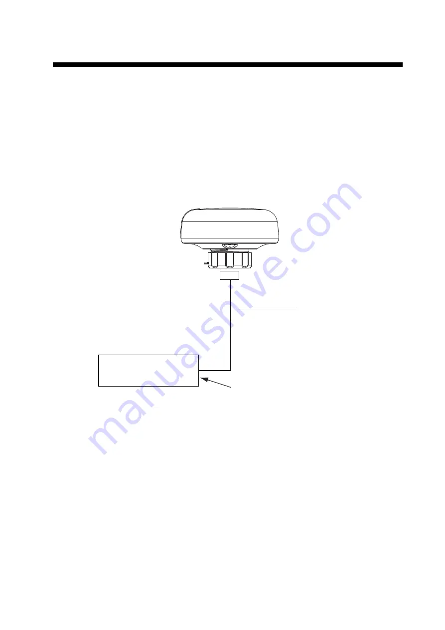
Insert the contact pin (supplied) into the #5 socket of the GPS Receiver connector to activate the
termination resistor. (See page 8 for location of #5 socket.) Route the cable assembly to the CAN
bus device. Coil any excess cable and secure it with a cable tie to prevent damage. Connect the
cable assembly to the CAN bus device.
Cable Assembly
33-1209-01 (6 m)
33-1209-02 (10 m, option)
GP-330B
Termination
Resistor: ON
* Cut plug from cable and connect
wires to terminal/connector.
- Radar Sensor*
- FI-50 Series Instrument
Содержание GP-330B
Страница 1: ...GP 330B www furuno com 取 扱 説 明 書 GPS RECEIVER GPS受信機 OPERATOR S MANUAL Model Part no 17 468 01 rev 05 ...
Страница 2: ......
Страница 22: ......
Страница 42: ...A 3 ...
Страница 43: ... CT 4 UWOK D 1 ...
Страница 44: ... CT 4 UWOK D 2 ...
Страница 45: ... CT 4 UWOK D 3 ...
Страница 46: ...S 1 ...
Страница 51: ......


