background image

7-6

5. Select AUTO or MANU and press the

[ENT]  key.  For  automatic  magnetic
variation, current  magnetic variation
appears to the right of AUTO.

6. If you selected AUTO, no further opera-

tion is necessary; press the [MENU] key
twice to finish. For MANU, press the
[ENT] key and enter magnetic variation
as follows:

a) If necessary, change coordinate from

east to west or vice versa by press-
ing 

 or 

.

b) Enter variation in two digits with the

cursor pad, referring to a nautical
chart.

c) Press the [ENT] key.
d) Press the [MENU] key twice to fin-

ish.

7.5 Geodetic Chart System

Your unit is preprogrammed to recognize
most of the major chart systems of the
world.  Although the WGS-84 system, the
GPS standard, is now widely used other
categories of charts still exist. Select the
chart system used, not the area where your
boat is sailing. The default chart system is
WGS-84.

1. Press the [MENU] key once or twice to

open the menu.

2. Select SYS SETUP and press the [ENT]

key.

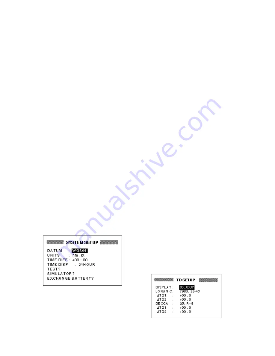
Figure 7-10 SYSTEM SETUP menu

3. Press the [ENT] key.

4. Select WGS84, (GPS standard) WGS72

or OTHER as appropriate and press the
[ENT] key.

5. If  you  selected  WGS72  or WGS84,

press the [MENU] key twice to finish. For
OTHER, do the following:

a) Press the [ENT] key.
b) Select chart number referring to the

geodetic chart list on page A-5.

c) Press the [ENT] key.
d) Press the [MENU] key twice to fin-

ish.

7.6 Units of Measurement

Distance/speed can be displayed in nauti-
cal miles/knots, kilometers/kilometers per
hour, or miles/miles per hour.

1. Press the [MENU] key once or twice to

open the menu.

2. Select SYS SETUP and press the [ENT]

key.

3. Select UNITS.

4. Press the [ENT] key.

5. Choose combination desired; nm, kt;

nm, km/h; mi, mi/h.

6. Press the [ENT] key.

7. Press the [MENU] key twice to finish.

7.7 Position Display Format

Position may shown in Lat./Long., TDs (Lo-
ran C or Decca) as follows. Decca and Lo-
ran C chain data is preprogrammed.

1. Press the [MENU] key once or twice to

open the menu.

2. Select TD SETUP and press the [ENT]

key.

Figure 7-11 TD SETUP menu

Содержание GP-31

Страница 1: ...GPS NAVIGATOR DGPS NAVIGATOR GP 31 GP 36...

Страница 2: ...5 4200 FIRST EDITION FIRST EDITION MAY MAY 1999 1999 Printed in Japan Printed in Japan All rights reserved All rights reserved K K APR APR 26 2002 26 2002 PUB No PUB No OME 43990 OME 43990 00080877701...

Страница 3: ...s power cord which can cause fire or electrical shock Use the proper fuse A 1A fuse is provided in the power data cable Use only a 1A fuse use of a wrong fuse can result in equipment damage CAUTION D...

Страница 4: ...is compatible with the voltage rating of the equipment Connection of an incorrect power supply can cause fire or equipment damage The voltage rating of the equipment appears on the label above the pow...

Страница 5: ...1 Arrival Alarm Anchor Watch Alarm 6 1 6 2 XTE Cross Track Error Alarm 6 2 6 3 Speed Alarm 6 3 6 4 DGPS Alarm 6 3 6 5 Time Alarm 6 3 6 6 Trip Distance Alarm 6 4 6 7 Buzzer Type Selection 6 4 7 OTHER...

Страница 6: ...consists of a display unit and an antenna unit The GP 36 additionally has a DGPS beacon receiver built in its display unit The high sen sitivity GPS receiver tracks up to twelve sat ellites simultane...

Страница 7: ...v SYSTEM CONFIGURATION GP 36 System configuration GP 31 System configuration...

Страница 8: ...0 A P G t i n u y a l p s i d g n i x i f r o f s c p 4 w e r c s g n i p p a T 1 8 0 2 0 8 0 0 0 o N e d o C 0 2 X 5 e p y T s t r a P e r a p S t e s 1 A 1 G M G F e p y T s c p 2 e s u F 5 0 8 4 1...

Страница 9: ...the display for adjustment of dimmer and contrast Inscribes mark MOB mark on the display Sets cancels destination Registers items on menus Cursor Pad Shifts cursor and display Selects items on menus M...

Страница 10: ...D r o f x e d n i e h T n o i s i c e r P f o n o i t u l i D e h t r e h g i h e h T y c a r u c c a g n i x i f n o i t i s o p e h t f o y c a r u c c a e h t r e h g i h e h t r e b m u n x i f n...

Страница 11: ...play Nav Data Display and User Display digital data or speedometer Press the DISP key to select a display mode Each time the key is pressed the display mode changes in the sequence shown below Figure...

Страница 12: ...p s track and shows position course speed and hori zontal display range setting Figure 1 4 Plotter display Highway display The highway display provides a 3 D view of own ship s progress toward destina...

Страница 13: ...information such as ship s speed course range bearing ETA and TTG Time To Go to destination Figure 1 6 Steering display Nav data display The nav data display shows position in latitude and longitude o...

Страница 14: ...he receiver status date and time indications The choices of data are speed course range bearing time to go estimated time of arrival trip distance and power source voltage Figure 1 8 Digital display S...

Страница 15: ...t menu item For example select the TRACK REC field 4 Press the ENT key A window showing options appears The figure below shows the options available for TRACK REC Figure 1 12 Options of TRACK REC 5 Pr...

Страница 16: ...3 Select SIMULATOR and press the ENT key Figure 1 16 SIMULATOR menu 4 Press the ENT key A window appears which shows the choices ON or OFF 5 Select ON and press the ENT key 6 Press the ENT key enter...

Страница 17: ...he ENT key and press the MENU key twice to finish Note If the power is reset while the simu lator display is in use the indication SIMU LATION MODE appears at the top of the screen at the next power u...

Страница 18: ...This page is intentionally left blank...

Страница 19: ...highway display mode is active 2 Press the ENT key The zoom window appears Figure 2 2 Zoom window 3 Press increase or decrease to select range desired 4 Press the ENT key to finish 2 2 Shifting the Cu...

Страница 20: ...TO CENTER 3 Press the ENT key 2 5 Changing Track Plotting Interval Stopping Plotting of Track To trace the ship s track the ship s position is stored into the memory at an interval of distance or auto...

Страница 21: ...rval as follows a Press the ENT key b Press or to select digit to change c Press or to change value d Press the ENT key after setting 6 Press the MENU key twice to finish 2 6 Erasing Track All track c...

Страница 22: ...This page is intentionally left blank...

Страница 23: ...regis ter the waypoint under that number and you do not need to change mark shape or enter a comment press the ENT key twice to register the waypoint and fin ish To enter KOBE as the waypoint name for...

Страница 24: ...eld press the ENT key select name with the cursor pad and press the ENT key 4 To change mark shape place the cur sor under MARK Press the ENT key select mark shape with the cursor pad and press the EN...

Страница 25: ...e date and time to the com ment of your choice press the ENT key enter comment and press the ENT key again 11 Place the cursor on Exit Press the ENT key 12 Press the MENU key twice to finish 3 2 Enter...

Страница 26: ...ypoint name mark shape and comment can be edited on the WPTS MRKS List 1 Press the MENU key once or twice to display the menu 2 Select WAYPOINTS and press the ENT key 3 Select LIST or NEAREST and pres...

Страница 27: ...the WAYPOINTS MARKS field Press the ENT key Figure 3 15 ERASE WP MRK display 4 Select the waypoint you want to erase Note You cannot erase CURSOR MOB or START 5 Press the ENT key A screen showing pos...

Страница 28: ...This page is intentionally left blank...

Страница 29: ...easiest method by which to create a route 1 Use the cursor pad to place the cursor on position desired Cursor position is shown at the bottom of the screen 2 Press the ENT key The following win dow ap...

Страница 30: ...press the ENT key The screen shown in Figure 4 7 ap pears Figure 4 7 Screen for entering route 5 Press and the ENT key to change route name if desired If no name is entered the name of the first and...

Страница 31: ...NT key Figure 4 11 Waypoints marks list 4 Select a waypoint and press the ENT key Your screen should look something like the one in Figure 4 11 Figure 4 12 Waypoint data screen 5 Select LOG RT and pre...

Страница 32: ...ved from the LOG field and is registered under the next se quential route number Note You can create a route using a com bination of current positions and waypoint positions including cursor position...

Страница 33: ...U key once or twice to display the menu 2 Select ROUTES and press the ENT key 3 Select the route from the ROUTES list 4 Press the ENT key 5 Select the waypoint which will come af ter the waypoint to b...

Страница 34: ...nder the starting and final destination waypoints You can change the comment as below Up to 16 characters may be used 1 Press the MENU key or twice to dis play the menu 2 Select ROUTES and press the E...

Страница 35: ...e 5 2 Cursor appearance when setting destination by cursor 4 Place the cursor on the location desired for destination 5 Press the ENT key A dashed line connects own ship and the destination which is m...

Страница 36: ...Point 2 WPT 002 ROUTE 01 KOBE Starting point Intermediate Point 1 WPT 001 Intermediate Point 1 WPT 003 OSAKA Arrival point FORWARD REVERSE Figure 5 7 Meaning of forward and reverse Current position b...

Страница 37: ...e fol lowing keying sequence MENU once or twice MESSAGE ENT The message board is discussed in paragraph 8 2 Dis playing the Message Board Figure 6 1 Location of alarm message and icon 6 1 Arrival Alar...

Страница 38: ...rent position as destination waypoint 1 Press the MENU key once or twice to open the menu 2 Select ALARMS 3 Press the ENT key 4 If ANC is not selected from the ARV ANC field select the ARV ANC field a...

Страница 39: ...the message SPD ALARM and the alarm icon appear To dis able the alarm select OFF at step 5 6 4 DGPS Alarm This alarm alerts you by aural and visual alarms when the DGPS beacon signal is lost 1 Press t...

Страница 40: ...o finish When the boat has traveled further than the preset trip distance the buzzer sounds and the message TRIP ALARM and the alarm icon appear To disable the trip alarm se lect OFF at step 5 6 7 Buz...

Страница 41: ...AUTO uses ship s average speed MANU is for manual entry of speed 11 Press the ENT key 12 If you selected MANU press the ENT key again Enter speed with the cursor pad and press the ENT key Figure 7 4...

Страница 42: ...ea con receiver and is set at the factory for automatic beacon receiver operation To manually adjust the GP 36 s beacon re ceiver or set up the GP 36 or GP 31 to use an external DPGS beacon receiver d...

Страница 43: ...ST do one of the follow ing MANUAL a The cursor is now on the RATE field Press the ENT key b Select the transmission rate of the DGPS beacon station to be used among 50 100 or 200 bps Press the ENT ke...

Страница 44: ...key twice to open the menu 2 Select DGPS and press the ENT key 3 Select STATION and press the ENT key 4 Select LIST and press the ENT key 5 Select USER and press the ENT key 6 Select a station from t...

Страница 45: ...netic bear ings 1 Press the MENU key once or twice to open the menu 2 Select PLOTTER 3 Press the ENT key Figure 7 8 PLOTTER SETUP menu 4 Select the BRG REF field 5 Press the ENT key The following win...

Страница 46: ...ice to open the menu 2 Select SYS SETUP and press the ENT key Figure 7 10 SYSTEM SETUP menu 3 Press the ENT key 4 Select WGS84 GPS standard WGS72 or OTHER as appropriate and press the ENT key 5 If you...

Страница 47: ...s the ENT key d If necessary enter TD offsets in ap propriate TD field s to refine position accuracy 7 Press the MENU key twice to finish 7 8 Time Difference using local time GPS uses UTC time If you...

Страница 48: ...ging Calculation of ETA and TTG etc is based on average ship s speed over a given pe riod If the period is too long or too short calculation error will result Change this setting if calculation error...

Страница 49: ...L or SPDOMETER as appropriate and press the ENT key 5 The cursor is now on the LARGE TOP field LARGE means the center indica tion on the digital display TOP is the indication below receiver status and...

Страница 50: ...or twice to open the menu 2 Select I O SETUP and press the ENT key 3 Select WIRING INFO and press the ENT key to display the wiring diagram Figure 7 20 Connection of GP 36 GP 31 to PC using a DSUB 9...

Страница 51: ...24 SAVING START prompt 5 Setup the computer to receive data 6 Press the ENT key Figure 7 25 Displays when downloading data 7 Press any key to escape Uploading data from a PC Note that all waypoint an...

Страница 52: ...LOAD WP YEOMAN 3 Press the ENT key Figure 7 30 LOAD WP RTE display 4 Press the ENT key Figure 7 31 LOADING START prompt 5 Set up the YEOMAN to output data 6 Press the ENT key Figure 7 32 Display when...

Страница 53: ...data format 1 Number of sentences required for one complete route data 1 to 4 See Note 2 Number of sentences currently used 1 to 4 3 Message mode Always set to C 4 Route No 01 to 51 51 is LOG route 2...

Страница 54: ...ting is 24 hour notation AM or PM is shown when 12 hour notation is selected 1 Press the MENU key once or twice to open the menu 2 Select SYS SETUP and press the ENT key 3 Select TIME DISP and press t...

Страница 55: ...en the menu 2 Select MESSAGES 8 MAINTENANCE TROUBLESHOOTING 3 Press the ENT key Figure 8 1 MESSAGE board 4 Press the MENU key twice to quit the message board Messages Table 8 1 Messages and their mean...

Страница 56: ...ceiver battery RTC keyboard and LCD for proper operation 1 Press the MENU key once or twice to open the menu 2 Select SYS SETUP and press the ENT key 3 Select TEST and press the ENT key You are asked...

Страница 57: ...ay unit and it pre serves data when the power is turned off The life of the battery is about 3 5 years When its voltage is low BATTERY ALARM appears on the display to alert you When this happens do th...

Страница 58: ...DATA MENU SETTINGS or ALL BACKUP DATA as appropriate and press the ENT key One of the fol lowing messages appears Figure 8 9 Prompt for erasure of GPS data menu settings backup data 4 Press the ENT k...

Страница 59: ...nnector you may unfas ten the connector with a needle nose pliers and 3 8 inch open end wrench Refasten it as shown in Figure 9 2 after running the cable through the hole Center pin soldered Clamp nut...

Страница 60: ...he power of this equipment is not iso lated thus the earth lamp may light when the antenna unit GPA 018 is grounded If it lights attach two capacitors 1mF 0 1mF in parallel to the antenna earth line E...

Страница 61: ...p t u O A G G K S M t u p n I f o a t a d n o i t c e r r o C n o c a e b l a n r e t x e r e v i e c e r l a n r e t n i f o t u p t u O s r e v i e c e r n o c a e b a t a d n o i t c e r r o c d n...

Страница 62: ...lected at step 4 NMEA REM1 NMEA REM2 NMEA AP For DATA1 NMEA REM NMEA AP RTCM OUT For DATA2 VER 1 5 VER 2 0 For NMEA Version BEACON displayed when DGPS setting is EXT Figure 9 6 Screens for setup of da...

Страница 63: ...AP 1 Menu Tree Default settings shown in boldface italic...

Страница 64: ...AP 2...

Страница 65: ...11 29 47 Western Russia 8000 10 25 50 65 North Central USA 8290 11 27 42 North Saudi Arabia 8990 11 25 40 56 69 Great Lakes 8970 11 28 44 59 South Central USA 9610 11 25 40 52 65 West Coast USA 9940...

Страница 66: ...orth Baltic 4B 33 Tohoku 6C 10 North West 4C 34 Kanto 8C Japan 11 Trondelag 4E 35 Shikoku 4C 12 English 5B 36 Hokuriku 2C 13 North Bothnian 5F 37 Kita Kyushu 7C 14 Southern Spanish 6A 38 Namaqualand 4...

Страница 67: ...orocco 081 MIDWAY ASTRO 1961 Midway Is 082 MINNA Nigeria 083 NAHRWAN Masirah Is 0man 084 United Arab Emirates 085 Saudi Arabia 086 NAMIBIA Namibia 087 MAPARIMA BWI Trinidad Tobago 088 NORTH AMERICAN 1...

Страница 68: ...d 6 Tracking velocity 999 kts 7 Position fixing time Warm start 12 seconds Cold start 90 seconds 8 Position Update Interval 1 second 9 Beacon Receiver GP 36 Frequency range 283 5 to 325 0 kHz MSK rate...

Страница 69: ...GPS RTCM SC 104 GP 36 only Downloading to PC WP Route Data Input Data DGPS RTCM SC 104 Ver 2 1 Uploading from PC WP Route Data NMEA WPL WP Data 5 POWER SUPPLY 1 GP 31 12 24 VDC 0 12 0 06 A at max leve...

Страница 70: ......

Страница 71: ......

Страница 72: ......

Страница 73: ......

Страница 74: ......

Страница 75: ......

Страница 76: ......

Страница 77: ......

Страница 78: ...6 DIM PWR key 1 2 Dimmer 1 2 Display modes 1 3 1 6 Display shift 2 2 G Geodetic chart list AP 5 Geodetic chart system 7 6 GPS satellite monitor display 8 2 H Highway display 1 4 I Installation 9 1 9...

Страница 79: ...7 Time display 7 14 Track erasing 2 3 plotting interval 2 2 starting stopping plotting 2 2 Trip alarm 6 4 Trip distance reset 7 10 True bearing 7 5 U Units of measurement 7 6 Uploading downloading dat...

Страница 80: ......

Страница 81: ......

Отзывы: