Furuno FM-4800 Скачать руководство пользователя страница 38

FM-4800 Operator’s Manual 

DIGITAL SELECTIVE CALLING 


29 


4.7.1 

How to Initiate a Position Request Call 

Enter the position request page 

Step 1


On the home screen, press the 

Menu/DSC

 control to enter the "MAIN 

MENU" page on the screen. 
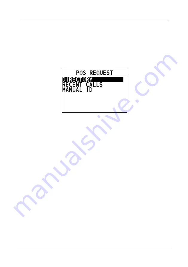
Step 2


Go to "DSC CALL > POS REQUEST". 
The "POS REQUEST" page appears on the radio screen.   


Initiate a position request call to a vessel registered in the 
directory 

Before you initiate a position request call from the individual directory, a vessel or 
person's name and the MMSI number associated with the vessel you want to 
transmit the call should be added to the individual directory. For information about 
how to add entries to individual directory, see section 12.1.1 Adding an Entry. 

Step 1


On the "POS REQUEST" page, press the 

Menu/DSC

 control to select 

"DIRECTORY". 

Step 2


Select an individual contact, and then press the 

Menu/DSC

 control. 


When CH70 is busy, you can wait without pressing any key until CH70 
is idle. 


When the CH70 is idle, the radio waits for an acknowledgement. 

Step 3


When the radio receives an acknowledgement, the radio screen shows 
the requested position information. Select the "OK" soft key or the 

Back


key to return to the home screen. 

Содержание FM-4800

Страница 1: ...MARINE VHF RADIOTELEPHONE FM 4800 OPERATOR S MANUAL www furuno com Model...

Страница 2: ...the equipment is acting abnormally or giving off strange noises immediately turn off the power at the switchboard and contact a FURUNO service technician Do not disassemble or modify the equipment Fi...

Страница 3: ...ful interference to radio communications However there is no guarantee that interference will not occur in a particular installation If this equipment does cause harmful interference to radio or telev...

Страница 4: ...etic compass Standard compass Steering compass 0 65 m 0 40 m FM 4800 0 70 m 0 45 m HS 4800 2 65 m 1 75 m SP 4800 ISEDC exposition aux radiations Cet quipement est conforme avec ISEDC les limites d exp...

Страница 5: ...r service marks of their re spective holders How to discard this product Discard this product according to local regulations for the disposal of industrial waste For disposal in the USA see the homepa...

Страница 6: ...14 4 3 2 How to Receive a DSC Distress Call 17 4 4 Individual Call 17 4 4 1 How to Initiate an Individual Call 18 4 4 2 How to Receive an Individual Call 20 4 5 Group Call 22 4 5 1 How to Initiate a G...

Страница 7: ...djusting the Backlight 56 10 1 2 Adjusting the Contrast 56 10 2 Units 56 10 2 1 Time Format 56 10 2 2 Time Offset 57 10 2 3 Speed 58 10 2 4 Bearing 58 10 3 Key Beep 58 10 4 GNSS Setup 59 10 4 1 Enteri...

Страница 8: ...73 12 5 Position Acknowledgement 73 12 6 Test Acknowledgement 74 12 7 Auto Position Interval 74 12 8 Timeout 74 13 ATIS SETUP 76 13 1 How to Enter the ATIS ID 76 13 2 How to Enable Disable the ATIS Fe...

Страница 9: ...tor s Manual iv 15 4 7 NMEA2000 Connector CAN bus connector 95 15 4 8 Extension Cable Optional 95 CHANNEL ASSIGNMENTS 97 MENU TREE 106 SPECIFICATIONS 109 PACKING LIST 112 OUTLINE DRAWINGS 116 INTERCON...

Страница 10: ...this manual We would appreciate feedback from you the end user about whether we are achieving our purposes Thank you for considering and purchasing FURUNO Features FURUNO FM 4800 Marine VHF Radiotelep...

Страница 11: ...ual 2 Program No FM 4800 0550257 01 HS 4800 0550259 01 denotes minor modifications CE declaration With regards to CE declarations please refer to our website www furuno com for further information abo...

Страница 12: ...CONFIGURATION 12VDC NavNet TZtouch 2 External Speaker Horn Speaker NAV EQUIPMENT NMEA2000 NMEA0183 MICROPHONE MIC 4800 HANDSET HS 4800 EXTENSION CABLE SPEAKER SP 4800 VHF ANT Standard Supply Optional...

Страница 13: ...the present seaworthiness and condition of your vessel Step 8 Give your vessel s description length design power or sail color and other distinguishing marks Step 9 Say over to end the message Release...

Страница 14: ...say over and release the PTT switch on the microphone When all communication with the vessel is completed end the last transmission by stating your call sign and the word out Note that you do not need...

Страница 15: ...ESS Distress Key Short press Enter the distress nature selection and position manual input menu Long press Press the DISTRESS key for 4 seconds to send a distress call 2 VOL SQL Volume Squelch Control...

Страница 16: ...the display setup mode Long press Power on or power off 5 Back Key On the home screen No function On other screens Short press Clear entries cancel calls backspace the cursor or back up to the previo...

Страница 17: ...ue to a stuck PTT key In addition Power is automatically reduced to protect against overheating due to continuous transmission 2 Cursor Key Changes the channel up or down 3 HI LO High Low Power Switch...

Страница 18: ...sion time is limited to five minutes This limits unintentional transmissions due to a stuck PTT key In addition Power is automatically reduced to protect against overheating due to continuous transmis...

Страница 19: ...s Press the DISTRESS key for 4 seconds to send a distress call 6 Back Key On the home screen No function On other screens Short press Clear entries cancel calls backspace the cursor or back up to the...

Страница 20: ...rnal GNSS are not fixed 3 indicates unread DSC messages 4 indicates the dual watch mode indicates the triple watch mode 5 This icon appears if user selects START of AUTO POS POLLING ACTIVATION This ic...

Страница 21: ...be used 3 NMEA0183 If no valid GNSS data from both the build in sensor and NMEA2000 the GNSS data from NMEA2000 will be used 11 In non scan mode display CH NAME In scan mode SCAN ALL indicates that t...

Страница 22: ...tress urgency safety routine position request position transmit and group calls to or from another vessel equipped with a DSC radio 4 2 Maritime Mobile Service Identity 4 2 1 What Is an MMSI An MMSI i...

Страница 23: ...r the MMSI number see section 4 2 2 How to Enter Your MMSI Number Initiate a DSC distress call without specifying the nature of distress The FM 4800 can transmit a DSC distress call without specifying...

Страница 24: ...g Listing Sinking Adrift Abandoning Piracy and MOB Man Overboard Step 1 Open the cover labeled DISTRESS Step 2 Short press the Distress key The DISTRESS screen appears Step 3 Select NATURE The NATURE...

Страница 25: ...l is sent the radio waits for an acknowledgement with the display showing AWAIT ACK If no acknowledgement is received the distress signal is repeated at 3 5 to 4 5 minute intervals until a DSC acknowl...

Страница 26: ...tress call is received the emergency alarm sounds Rotate the Menu DSC control to stop the alarm Step 2 Optional The display shows the MMSI of the vessel in distress To show additional information of t...

Страница 27: ...IDUAL page appears on the screen Initiate an individual call to a vessel registered in the individual directory Before you initiate an individual call from the individual directory a vessel or person...

Страница 28: ...can wait without pressing any key until CH70 is idle A1 indicates the alias of called party If the called party has no alias the MMSI of called party will appear When the CH70 is idle the radio waits...

Страница 29: ...about how to set the channel change mode see section 12 3 Channel Change Mode When the channel change mode is AUTO Step 1 When an individual call is received the alarm sounds Rotate the Menu DSC contr...

Страница 30: ...conversation Note If no key is pressed within 10 seconds the radio automatically sends an acknowledgement and switches to the requested channel when CH70 is idle Otherwise the radio will wait until C...

Страница 31: ...e requested channel is selected ready for a conversation Step 3 Press and hold the PTT key to talk into the microphone 4 5 Group Call This feature allows you to contact a group of specific vessels for...

Страница 32: ...of entries is 40 Initiate a group call to a group registered in the directory Step 1 On the GROUP page select DIRECTORY Step 2 Select a group and then press the Menu DSC control to enter the SELECT C...

Страница 33: ...Step 3 Select a channel Step 4 Press the Menu DSC control to initiate a group call When CH70 is busy you can wait without pressing any key until CH70 is idle When the CH70 is idle the radio waits for...

Страница 34: ...o the requested channel Step 3 Press and hold the PTT key to talk into the microphone When the channel change mode is MANUAL Step 1 When a DSC Distress Alert is received the alarm sounds Rotate the Me...

Страница 35: ...gency call This type of call is used when a vessel may not truly be in distress but has a potential problem that may lead to a distress situation This call is the same as saying Pan Pan Pan on CH16 4...

Страница 36: ...see section 12 3 Channel Change Mode When the channel change mode is AUTO Step 1 When an All Ships call is received an emergency alarm sounds Rotate the Menu DSC key to stop the alarm The following s...

Страница 37: ...he channel change mode is MANUAL Step 1 When an All Ships call is received an emergency alarm sounds Press any key to stop the alarm The following screen appears The screen shows the MMSI of the vesse...

Страница 38: ...and the MMSI number associated with the vessel you want to transmit the call should be added to the individual directory For information about how to add entries to individual directory see section 1...

Страница 39: ...CALLS Step 2 Select an individual contact and then press the Menu DSC control When CH70 is busy you can wait without pressing any key until CH70 is idle When the CH70 is idle the following screens ap...

Страница 40: ...owledgement Step 3 When the radio receives an acknowledgement the radio screen shows the requested position information Select the OK soft key or the Back key to return to the home screen Note If the...

Страница 41: ...H70 is idle When CH70 is idle the radio sends an acknowledgement and the position is transmitted Step 3 After the position is transmitted select OK to return to the home screen When POSITION ACK is se...

Страница 42: ...Enable the Auto Position Polling Step 1 On the home screen press the Menu DSC control to enter the MAIN MENU screen Step 2 Go to DSC CALL AUTO POS POLLING The AUTO POS POLLING page appears on the scre...

Страница 43: ...t SELECT ADDRESS The SELECT ADDRESS page appears on the screen You can add at most four directories Step 4 Select a directory Note You need to select at least one directory first to start the auto pos...

Страница 44: ...cate an unread received call message The FM 4800 can store logs for the latest 40 received distress calls the latest 10 received position request calls the latest 40 received other calls the latest 40...

Страница 45: ...her DSC radio To use this feature the radio that you send the test call to must have the DSC Test feature Note To make a DSC test call this vessel s MMSI number must be entered into the radio For info...

Страница 46: ...the MMSI number associated with the vessel you want to transmit the call to should be added to the individual directory For information about how to add entries to individual directory see section 12...

Страница 47: ...revious screen Initiate a DSC test call from the RECENT CALLS Step 1 On the DSC TEST page select RECENT CALLS Step 2 Select an individual contact Step 3 Press the Menu DSC control to send the DSC test...

Страница 48: ...NUAL ID Step 2 Rotate and press the MENU DSC control to enter the MMSI of a vessel that you want to contact Step 3 Press the Menu DSC control to send the DSC test call Your radio waits for an acknowle...

Страница 49: ...l to adjust the squelch until the background noise disappears Step 2 On the home screen rotate the Menu DSC control to select a channel to DUAL CH with CH16 Step 3 Press the Menu DSC control to enter...

Страница 50: ...h control to adjust the squelch until the background noise disappears Step 2 On the home screen rotate the Menu DSC control to select a channel to watch with CH16 and the second priority channel Step...

Страница 51: ...nnels Step 1 On the home screen press the Menu DSC control to enter the MAIN MENU screen Step 2 Go to SCAN SCAN ALL 16 The radio starts to scan all channels in sequence and checks CH16 after each prog...

Страница 52: ...er each memory channel Step 3 To stop scanning press the Back key or the Menu DSC control 6 5 Editing Memory Channel List This feature allows you to add channels to or remove channels from the memory...

Страница 53: ...nel to be scanned Step 4 Press the Menu DSC control to set the channel to a memory channel The MEM icon appears on the display Step 5 Press the Back key to return to the previous screen How to remove...

Страница 54: ...ENU screen appears Step 2 Select WEATHER MODE The weather mode page appears on the screen indicates weather alert is ON In weather mode you can rotate the Menu DSC to select a NOAA channel to monitor...

Страница 55: ...Weather Mode FM 4800 Operator s Manual 46 Step 3 Select ON or OFF to enable or disable the feature Step 4 Press the Menu DSC control to save the setting and return to the previous page...

Страница 56: ...andard fog horn tones through the speaker This feature is available only when the radio is connected to a hailer Enter the FOG HORN page Step 1 On the home screen press the Menu DSC control to enter t...

Страница 57: ...Step 2 Press and hold the PTT key to sound the alarm Step 3 To stop the alarm release the PTT key Step 4 Press the Back key to return to the previous screen Use the auto horn The Auto Horn feature all...

Страница 58: ...or emergency siren Underway For power driven vessels underway One 5 second blast at 120 second interval Stopped For power driven vessel that is stationary Two 3 second blasts with a 2 second interval...

Страница 59: ...For vessels at anchor A rapidly ringing bell tone sounds for about 5 seconds repeated at an interval of 60 seconds 5s 60s Anchored Signal Aground For vessels aground Two bell tones of 0 5 seconds a b...

Страница 60: ...n to the response from the hailer Step 1 On the home screen press the Menu DSC control to enter the MAIN MENU screen Step 2 Go to FOG HAILER IC HAILER The HAILER page appears on the screen You can adj...

Страница 61: ...ween the radio and a handset This feature is available only when your radio is equipped with handset or a microphone Step 1 On the home screen press the Menu DSC control to enter the MAIN MENU screen...

Страница 62: ...y to return to the previous screen 8 4 Edit Handset Name You can customize the handset name after the handset connects to the product remotely After that the handset name is saved and displayed on any...

Страница 63: ...Manual 54 Step 4 Select a desired handset Step 5 Rotate and press the Menu DSC control to enter a new handset name for the current selected handset Step 6 Press the Menu DSC control to save the new ha...

Страница 64: ...55 9 SETTING MMSI You can register a MMSI and view the registered MMSI For information about how to set MMSI number of your vessel see section 4 2 2 How to Enter Your MMSI Number...

Страница 65: ...BACKLIGHT Step 4 Rotate the Menu DSC control to adjust the backlight 10 1 2 Adjusting the Contrast Step 1 On the home screen press the Menu DSC control to enter the MAIN MENU screen Step 2 Go to GENER...

Страница 66: ...ffset This feature allows you to set the time difference between UTC and local time if you want to use local time The offset is added to or subtracted from the time received from the GNSS receiver or...

Страница 67: ...SPEED Step 3 Select a unit Step 4 Press the Menu DSC control to save the setting and return to the previous page 10 2 4 Bearing This feature allows you to set the mode magnetic or true Note A GNSS rec...

Страница 68: ...s page 10 4 GNSS Setup This section allows you to set how to show the time and the position information of the vessel 10 4 1 Entering the GNSS SETUP Page Step 1 Press the Menu DSC control until the MA...

Страница 69: ...Speed Over Ground SOG on the radio screen Step 1 In the GNSS SETUP page select COG SOG DISPLAY The following page appears on the screen Step 2 Select ON or OFF Step 3 Press the Menu DSC control to sa...

Страница 70: ...tes available for NMEA0183 When AIS OUTPUT is set to ON the baud rate is 38400 When AIS OUTPUT is set to OFF the baud rate is 4800 10 5 1 Entering the I O PORT SETUP Page Step 1 Press the Menu DSC con...

Страница 71: ...et whether to output the GNSS data Step 1 In the I O PORT SETUP page select GNSS OUTPUT The following page appears on the screen Step 2 Select ON or OFF Step 3 Press the Menu DSC control to save the s...

Страница 72: ...AIS data Step 1 In the I O PORT SETUP page select AIS OUTPUT The following page appears on the screen Step 2 Select ON or OFF Step 3 Press the Menu DSC control to save the setting and return to the p...

Страница 73: ...ure allows you to test items as shown in the following table You can also see explanations of testing results in the following table Testing Item Explanation of Testing Result GNSS OK There is a GNSS...

Страница 74: ...ORY RESET page appears on the screen Step 2 Select whether to reset the items to factory settings If you select YES the radio will restart and is reset to factory settings If you select NO the radio r...

Страница 75: ...rs Step 2 Go to CH FUNCTION SETUP CH GROUP The following page appears on the screen Step 3 Select INTERNATIONAL USA or CANADA Step 4 Press the Menu DSC control to save the setting 11 2 Second Priority...

Страница 76: ...ode is in use the display shows a name under the channel number selected This is the name of the current channel You can customize channel names as follows Step 1 Press the Menu DSC control until the...

Страница 77: ...IVATE CH menu is available only when the channel group is set to INTERNATIONAL For information about how to set the channel group see section 11 1 Channel Group Step 1 Press the Menu DSC control until...

Страница 78: ...est calls 12 1 1 Adding an Entry You can add 200 entries at most Step 1 Press the Menu DSC control until the MAIN MENU screen appears Step 2 Go to DSC SETUP INDIV DIRECTORY The following page appears...

Страница 79: ...Step 2 Go to DSC SETUP INDIV DIRECTORY Step 3 Select the entry needing editing The following page appears on the screen Step 4 Select EDIT Step 5 Rotate and press the Menu DSC control to edit the entr...

Страница 80: ...creen 12 2 Group Directory This feature allows you to add edit or delete groups the radio belongs to 12 2 1 Adding an Entry Step 1 Press the Menu DSC control until the MAIN MENU screen appears Step 2...

Страница 81: ...entry Step 6 After you finish entering the information press the Menu DSC control to save the setting and return to the previous screen 12 2 3 Deleting an Entry Step 1 Press the Menu DSC control unti...

Страница 82: ...the acknowledgement mode of individual call requests Step 1 Press the Menu DSC control until the MAIN MENU screen appears Step 2 Go to DSC SETUP INDIVIDUAL ACK The INDIVIDUAL ACK page appears on the s...

Страница 83: ...CK page appears on the screen Step 3 Select MANUAL or AUTO MANUAL Select the soft key and then you need to send an acknowledgement manually upon a call request AUTO Select the soft key and then the ra...

Страница 84: ...appears Step 2 Go to DSC SETUP TIMEOUT The DSC SETUP page appears on the screen Step 3 Select TIMEOUT The TIMEOUT page appears on the screen Step 4 Select NON DISTRESS or RX DISTRESS Step 5 Do one of...

Страница 85: ...IS ID If you need to change the ID after it has been entered contact your dealer Step 1 Press the Menu DSC control until the MAIN MENU screen appears Step 2 Go to ATIS SETUP SET ATIS ID The following...

Страница 86: ...2 Select ATIS SETUP The ATIS SETUP page appears on the screen Step 3 Do one of the following To enable the ATIS feature select ON If you haven t entered the ATIS ID you are required to enter the ID f...

Страница 87: ...nuous use However take the following precautions to prevent damage to the radio Keep the microphone connected or the jack covered at all times to prevent corrosion of electrical contacts Remove dust f...

Страница 88: ...k wire is connected to the negative battery post Step 2 Check the power cable for DC voltage and replace the fuse 8A 250V The speaker makes popping or whining noise while the engine of the ship runs E...

Страница 89: ...the GNSS receiver Choose the proper information to check If the NMEA2000 or NMEA0183 cable is connected make sure that the output of the cable is valid If the NMEA2000 or NMEA0183 cable is not connec...

Страница 90: ...2pcs Optional supply Name Type Code no Remarks Handset HS 4800 001 468 560 Handset Hanger Installation Materials Accessories Speaker SP 4800 001 468 580 Speaker Installation Materials Accessories Ext...

Страница 91: ...972 11 w connector heavy 2m CB 05BFFM 060 000 167 973 11 w connector heavy 6m Connector for NMEA2000 FRU MM1MF1MF1001 001 507 050 T Connector Micro style 3 NC 050505 FMF TS001 000 160 507 10 Mini sty...

Страница 92: ...the radio to the hanger Step 4 Tighten the knob bolts on both sides of the hanger For flush mounting Step 1 Determine the position of installation holes according to the marking template and drill the...

Страница 93: ...ocation where it is easy to install the FM 4800 radio Step 2 Fix the hanger with four screws Step 3 Set the radio to the hanger Step 4 Tighten the knob bolts on both sides of the hanger Hanger Radio H...

Страница 94: ...easy to install the microphone hanger Step 2 Fix the hanger with two screws Step 3 Place the microphone into the hanger 15 2 3 How to Install the Handset Optional Step 1 Determine a location where it...

Страница 95: ...the hanger Step 5 Connect the signal cable For flush mounting Step 1 Determine the position of installation holes according to the marking template and drill the hole Step 2 Pry off the frame from the...

Страница 96: ...FM 4800 Operator s Manual INSTALLATION 87...

Страница 97: ...INSTALLATION FM 4800 Operator s Manual 88 15 3 Soft Cover Slightly press the four corners in circle and plastic in rectangular in place 15 4 Wiring 15 4 1 Overview...

Страница 98: ...d be placed in a position which is as elevated and free as possible with at least 2 meters horizontal separation from constructions made by conductive materials Ideally there should not be more than o...

Страница 99: ...ctor cover on the rear back of the unit Step 2 Insert the antenna cable into the antenna connector Step 3 Tighten the antenna hand tight Step 4 Secure the cable with the electrical cable Waterproofing...

Страница 100: ...e end of the Self bonding tape and wind it clockwise on the antenna head Step 4 Wrap around the cable 15 4 3 Ground Cable Step 1 Loosen the screw on the rear back of the unit Step 2 Place the groundin...

Страница 101: ...2 Referring to the figure below place heat shrink tubes on the wires and then solder the connection point Step 3 Move the heat shrink tubes to the soldered connection and then apply heat to the tubes...

Страница 102: ...ON 93 15 4 5 NMEA 0183 Wire The NMEA 0183 wire can be used to connect the unit to a third party GPS GNSS receiver or malfunction display The NMEA 0183 wire should be connected to a compatible NEMA 018...

Страница 103: ...cessary mount the speaker according to the installation provided with the device Step 2 Route or extend the wire from the speaker to the radio Step 3 Connect the purple wire on the radio wiring harnes...

Страница 104: ...ices onto the backbone cable to expand your network onboard With CAN bus Ids are assigned to all the devices in the network and the status of each sensor in the network can be detected All the CAN bus...

Страница 105: ...INSTALLATION FM 4800 Operator s Manual 96 Step 5 Fasten the three tapping screws Step 6 Fasten the cover on the extended cable and tighten it...

Страница 106: ...mercial Non commercial recreational 10 156 500 156 500 Simplex Commercial 11 156 550 156 550 Simplex Commercial VTS in selected areas 12 156 600 156 600 Simplex Port operation VTS in selected areas 13...

Страница 107: ...ge to bridge communications 68 156 425 156 425 Simplex Non commercial recreational 69 156 475 156 475 Simplex Inter ship Port Operations and Ship Movement 70 156 525 156 525 Digital selective calling...

Страница 108: ...t 1084 157 225 157 225 Simplex Inter ship digital only 1085 157 275 157 275 Simplex 1086 157 325 157 325 Simplex 2006 160 900 160 900 Simplex 2019 161 550 161 550 Simplex Port Operations Ship Movement...

Страница 109: ...156 300 156 300 Simplex Inter ship Safety 1007 156 350 156 350 Simplex Commercial VDSMS 08 156 400 156 400 Simplex Commercial Inter ship only VDSMS 09 156 450 156 450 Simplex Boater Calling Commercial...

Страница 110: ...900 Duplex Public Correspondence Marine Operator VDSMS 27 157 350 161 950 Duplex Public Correspondence Marine Operator VDSMS 28 157 400 162 000 Duplex Public Correspondence Marine Operator VDSMS 1063...

Страница 111: ...only 84 157 225 161 825 Duplex Public Correspondence Marine Operator VDSMS 85 157 275 161 875 Duplex Public Correspondence Marine Operator VDSMS 86 157 325 161 925 Duplex Public Correspondence Marine...

Страница 112: ...w power 1 W only 18A 156 900 156 900 Simplex Commercial 19A 156 950 156 950 Simplex Coast guard 20 157 000 161 600 Duplex Canadian coast guard only 21A 157 050 157 050 Simplex Canadian coast guard 21B...

Страница 113: ...69 156 475 156 475 Simplex U S non commercial recreational Canada commercial fishing only International inter ship port Operations and Ship Movement 70 156 525 156 525 Simplex Digital selective callin...

Страница 114: ...plex Public Correspondence Marine Operator 87 157 375 157 375 Simplex Port Operations Ship Movement 88 157 425 157 425 Simplex Port Operations Ship Movement Weather Channel Chart Only USA and Canada C...

Страница 115: ...DRESS MONITOR POSITION DSC LOG RX DISTRESS LOG RX POS REQ LOG RX OTHER LOG TX LOG TX ACK LOG DSC TEST DIRECTORY RECENT CALLS MANUAL ID CH WATCH DUAL CH TRIPLE CH SCAN SCAN ALL SCAN ALL 16 MEMORY SCAN...

Страница 116: ...FACTORY RESET FOG HORN FREQ 200Hz to 850Hz 400Hz SERVICE MENU Requires password access For service personnel only CH FUNCTION SETUP CH GROUP INTERNATIONAL USA CANADA 2ND PRIORITY CH 09 EDIT CH NAME P...

Страница 117: ...Operator s Manual 108 SQUELCH OFF 1 to 8 MAX 3 VOLUME OFF 1 to 14 MAX 1 HAILER VOLUME OFF 1 to 14 MAX 1 HAILER TAKING VOLUME OFF 1 to 14 MAX 1 HAILER LISTENING VOLUME OFF 1 to 14 MAX 1 INTERCOM VOLUME...

Страница 118: ...less than 0 25 W 2 5 Modulation 16K0G3E F3E Voice 16K0G2B F2B DSC 3 RECEIVER 3 1 Frequency Range 155 500MHz to 162 0375MHz Frequency range of Weather Channel 162 550 MHz to 163 275 MHz Only USA and C...

Страница 119: ...r speaker 30W max 4 ohm 15W 4 ohm 1kHz 12 0V 10 distortion 8 INTERFACE 8 1 Number of port NMEA0183 1 port NMEA2000 1 port 8 2 NMEA0183 Sentence Input DTM GGA GLL GNS RMA RMC Output DSC DSE GLL RMC VDM...

Страница 120: ...0 V DC 10 30 9 2 Power consumption Transmit 5 A at 25W output with all options Receive 2 5 A at 3W audio output Standby 1 A 10 ENVIRONMENTAL CONDITION 10 1 Ambient temperature 15 to 55 10 2 Relative...

Страница 121: ...PACKING LIST FM 4800 Operator s Manual 112 PACKING LIST...

Страница 122: ...FM 4800 Operator s Manual PACKING LIST 113...

Страница 123: ...PACKING LIST FM 4800 Operator s Manual 114...

Страница 124: ...FM 4800 Operator s Manual PACKING LIST 115...

Страница 125: ...OUTLINE DRAWINGS FM 4800 Operator s Manual 116 OUTLINE DRAWINGS FM 4800 Desktop mounting...

Страница 126: ...FM 4800 Operator s Manual OUTLINE DRAWINGS 117 FM 4800 Flush mounting...

Страница 127: ...OUTLINE DRAWINGS FM 4800 Operator s Manual 118 FM 4800 Hanger Mounting...

Страница 128: ...FM 4800 Operator s Manual OUTLINE DRAWINGS 119 MIC 4800 Desktop mounting and Bulkhead Wall...

Страница 129: ...OUTLINE DRAWINGS FM 4800 Operator s Manual 120 HS 4800 Desktop mounting and Bulkhead Wall...

Страница 130: ...FM 4800 Operator s Manual OUTLINE DRAWINGS 121 SP 4800 Desktop Mount...

Страница 131: ...OUTLINE DRAWINGS FM 4800 Operator s Manual 122 SP 4800 Flush mounting...

Страница 132: ...0m 1 NMEA2000 HS POWER RED BLACK 1 2 Power EXT SPK PURPLE GRAY 3 4 SPK Hailer RED BLACK Hailer 5 6 Hailer VCTF 1 25sq 2C MAX 20 0m 1 Speaker 8 1 Horn Speaker 4 1 Power 12VDC 1 2 0M 0 4M 0 4M SPK VCTF...

Страница 133: ...ty knife 2 Philips screwdriver 11 Wire stripper 3 Flathead screwdriver 12 Electric iron 4 Adjustable wrench 13 Heat shrink tube 5 Heat gun 14 Waterproof adhesive tape 6 Marker 15 Electric drill 7 Mult...

Страница 134: ...mpleto della dichiarazione di conformit UE disponibile al seguente indirizzo Internet Ar o Furuno Electric Co Ltd deklar ka augst k min ts radioiek rta atbilst Direkt vai 2014 53 ES FM 4800 ELi vastav...

Страница 135: ...skladnosti je na voljo na naslednjem spletnem naslovu O texto integral da declara o de conformidade est dispon vel no seguinte endere o de Internet A Furuno Electric Co Ltd patvirtinu kad pirmiau min...

Отзывы: