background image


21

VHW - Water speed and heading

$--VHW,x.x,T,x.x,M,x.x,N,x.x,K*hh<CR><LF>

                |   |    |    |   |    |    |   |   |

                |   |    |    |   |    |    |   |   +--------- 5

                |   |    |    |   |    |   +--+----------- 4

                |   |    |    |   +--+----------------- 3

                |   |    +--+----------------------- 2

               +--+----------------------------- 1

    1. Heading, degrees true

    2. Heading, degrees magnetic

    3. Speed, knots

    4. Speed, km/h

    5. Checksum

VLW - Distance traveled through water

$--VLW,x.x,N,x.x,N*hh<CR><LF>

               |    |    |   |   |

               |    |    |   |  +--------- 3

               |    |   +--+----------- 2

               +--+----------------- 1

    1. Total cumulative distance, nautical miles

    2. Distance since reset, nautical miles

    3. Checksum

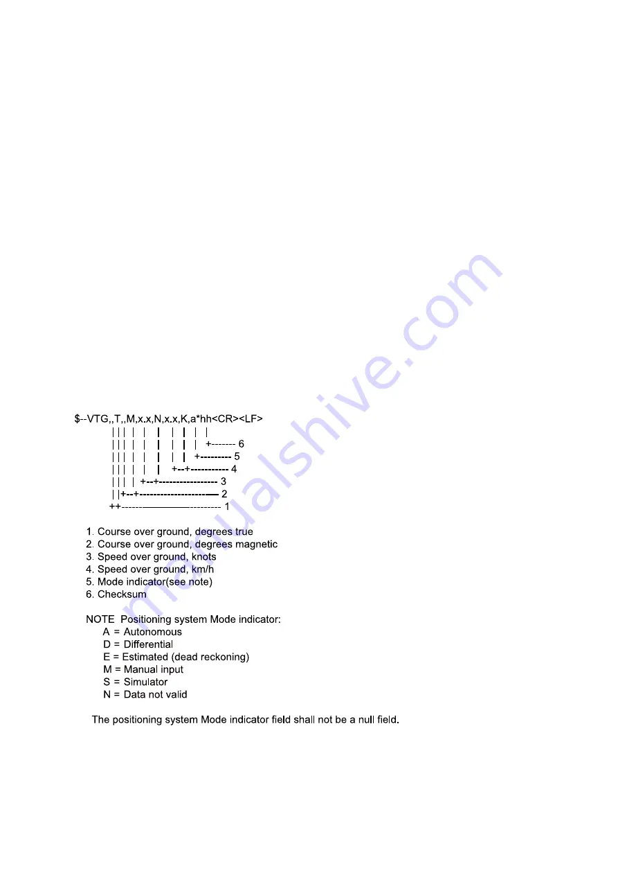
VTG - Course over ground and ground speed


Содержание DS-50

Страница 1: ...DOPPLER SPEEDLOG DS 50 OPERATOR S MANUAL www furuno com Model ...

Страница 2: ...ual is elemental chlorine free FURUNO Authorized Distributor Dealer 9 52 Ashihara cho Nishinomiya 662 8580 JAPAN A APR 1996 Printed in Japan All rights reserved P2 FEB 01 2019 Pub No OME 72410 P2 ETMI DS 50 0 0 0 8 0 7 5 6 8 1 3 ...

Страница 3: ...scard this product according to local regulations for the disposal of industrial waste For disposal in the USA see the homepage of the Electronics Industries Alliance http www eiae org for the correct method of disposal How to discard a used battery Some FURUNO products have a battery ies To see if your product has a battery ies see the chapter on Maintenance Follow the instructions below if a bat...

Страница 4: ...quipment Use of a wrong fuse can result in damage to the equipment Do not use the equipment for other than its intended purpose Improper use of the equipment can result in personal injury or equipment damage Turn off the equipment immediately if you feel it is abnormal Turn off the power from the switchboard if the equipment is emitting strange noises or becomes excessively hot Contact your dealer...

Страница 5: ... the labels If a label is missing or is illegible contacta FURUNO dealer or agent about replacement WARNING To avoid electrical shock do not remove cover No user serviceable parts inside Name Warning Label 1 Type 86 003 1011 1 Code No 100 236 231 MAIN DISPLAY UNIT DS 500 PROCESSOR UNIT DS 510 DS 511 TRANSCEIVER UNIT DS 520 Warning label ...

Страница 6: ...9 Selecting Unit of Speed Measurement 9 Displaying Distance Run or Keel Clearance 9 Setting Distance Run 10 System Settings 11 CONTROL BOX option OPERATION 13 MAINTENANCE TROUBLESHOOTING 14 Preventive Maintenance 14 Troubleshooting 15 Operation Checks 15 Error Displays 17 Program Number 17 PRINCIPLE OF DOPPLER SPEED LOG 18 DIGITAL INTERFACE IEC 61162 1 EDITION 2 19 LIST OF ABBREVIATIONS 22 Declara...

Страница 7: ...m arrangement for highly accurate and stable measurement Highly accurate speed measurement in shallow waters with under keel clearance as little as1 meter enabling close control of speed for safe berthing and anchoring operations Ground tracking speed measured between 1 and 200 meters for accurate speed measurement in coastal waters Wide variety of both analog and digital displays optionally avail...

Страница 8: ...inal viewing distance 1m Brilliance control Duty cycle of ON OFF 5 Input Output signals Input External keying pulse 2 ports Output Ship s speed 2 ports digital 1 port analog or through distribution box Distance signal 1 port 400 p NM forward data only Distance signal 6 ports with contact closure signal 200 p NM contact capacity 30 V max 0 2A forward data only Alarm signal 1 port contact closure si...

Страница 9: ...rent signal for analog display 1 board 2 5mA to 10 0 mA 10kn to 40kn or 3 33mA to 10 0mA 10kn to 30kn 3 OAD board Analog current signal for analog display 1 board 2 5mA to 10 0 mA 10kn to 40kn or 3 33mA to 10 0 mA 10kn to 30kn 4 OLG board For Distance Indicator 1 port 1 board and Log signal 3 ports 1 board 200 400 p NM contact closure signal 30V 0 2A or RS 422 current loop signal One Log signal po...

Страница 10: ...tion 1 Indication system Dual range system 2 Panel dimensions φ200 mm 3 Power consumption 5 VA approx Specifications of DS 501 Control Box option 1 Installation method Flush mount 2 Power consumption 200mW max 3 Illumination LED Specifications of DS 760 Series Analog Display option 1 Indication range 10 to 30kn 2 Panel dimensions DS 761 762 φ200 mm DS 763 φ100 mm 3 Power consumption 5 VA approx ...

Страница 11: ...ITAL DISPLAY ANALOG DISPLAY DISTANCE RUN INDICATOR JUNCTION BOX DS 360 option TRANSCEIVER UNIT DS 520 TRANSDUCER TANK DS 531 or GATE VALVE DS 532 TRANSDUCER DS 530 Note When Processor Unit DS 510 is used Transceiver Unit is incorporated in the DS 510 JUNCTION BOX CI 630 option TRANSDUCER TANK DS 331 TRANSDUCER DS 330 or GATE VALVE for TRANSDUCER DS 335 RANGE SWITCH BOX DS 389 HF 22A ANALOG INDICAT...

Страница 12: ...t or meters second Test mode indicator Fore and aft direction indicators Port and starboard direction indicators Port or starboard speed Fore or aft speed Tracking mode indicator Ground Water Automatic MODE selector Selects tracking mode Distance Keel Clearance selector Displays distance run or keel clearance kn m s selector Selects unit of speed measurement O N U R U F O N U R U F If a speed erro...

Страница 13: ...ng mode lamps Distance Keel Displays distance run or depth below keel at each pressing Clearance selector Distance or Keel Clearance lights to show current selection DIMMER controls Adjust panel brilliance Controls in compartment kn m s SET Distance Set POWER W X kn m s selector Selects the unit of speed measurement knots or meters second SET key Sets distance run display Arrow keys Set the distan...

Страница 14: ...each tested eight times consecutively Then the program version number of both the main display unit and the processor unit appear Keel Clearance m s fa NM kn ft Distance AL G W A S Program Version NO of main display unit Program Version NO of processor unit The equipment is normal if the program version nos appear If an error is found an error message appears instead of a program version number Er...

Страница 15: ...ng mode or water tracking speed mode depending on depth Water tracking mode is selected when the keel clearance exceeds 200 meters Note Actual working depth in the ground tracking mode depends on seabed and water conditions and the reflecting properties for sonic pulses Selecting Unit of Speed Measurement Speed can be measured in knots or meters second Press the kn m s selector to select the unit ...

Страница 16: ...king cursor on the digit to change 3 Press or to set 4 Repeat steps 2 and 3 to change other digits Note 1 Distance run can be reset to zero by entering all zeroes Note 2 To restore previous distance run setting do not operate arrow keys or SET key for more than 10 seconds When this is done the distance run indication stops blinking and then the previous setting is restored Note that if the ship is...

Страница 17: ...nsducer installation offset 12 8 to 12 7 0 1 steps 0 4 Trim angle offset 12 8 to 12 7 0 1 steps 0 0 5 Heel angle offset 12 8 to 12 7 0 1 steps 0 0 6 Speed averaging 15 30 60 90 sec 15 sec 7 Reference water speed depth 2 0 to 25 0 m 1 m steps 2 m 8 External KP1 distance 0 0 to 300 0 m 0 1 m steps 0 0 9 External KP2 distance 0 0 to 300 0 m 0 1 m steps 0 0 10 Unit of keel clearance measurement m ft f...

Страница 18: ...of the display DOPPLER SONAR DS 50 MODE Keel Clearance m s fa DIMMER NM kn ft Distance AL G W A S FURUNO FURUNO 1 appears Setting The number corresponds to that on the table on page 11 Hinged cover 2 Press or to select system setting number to be changed 3 Press W or X to change setting 4 Press or to verify the data entered 5 Turn off the power and the new settings are entered in memory ...

Страница 19: ...ROL BOX OPTION OPERATION The DS 501 Control Box provides remote operation of the main display unit The MODE Distance Keel Clearance and DIMMER controls function the same as those found on the main display unit ...

Страница 20: ...replace the coating with SEA GRANDPRIX 660HS To remove the current coating soak a nylon based scrubbing pad in thinners then apply the thinner to the coating in a washing motion To prevent damage to the transducer do not use tools scrapers etc or sandpaper to remove the coating SEATENDER 20 no other paint allowed anticorrosion paint ...

Страница 21: ...er cable Operation Checks Main display unit 1 Turn on the power whle pressing and holding down the MODE selector The following appears when the equipment is normal Port starboard speed 0 5 kn Fore aft speed 18 9 kn Distance run 12345 67 Depth 12 3 unit according to system settings 2 Operate the MODE Distance Keel Clearance and kn m s controls one by one Confirm that mode or indications changes wit...

Страница 22: ... equipment is normal if the program version no appears 1 To run the diagnostic program turn on the power while pressing the kn m s selector The program checks the LEDs ROM RAM EEPROM and buzzer and displays the program version number This is done continuously 2 To escape from the diagnostic program turn off the power Error display DOPPLER SONAR DS 50 MODE Keel Clearance m s fa DIMMER NM kn ft Dist...

Страница 23: ...error 3 EEPROM error 3 MIF Board Processor unit error indications 1 MCP Board error 2 MFT Board error error Program Number Pub No Modification Date Software Program No OME 72410 K Modified to fix VTG sentence 7 2002 DS 500 VCP board 665 0400 003 DS 510 MCP board 665 0410 007 MFT board 665 0120 000 MIF board 665 0122 001 OME 72410 P Modified for IEC62288 MAR 2010 DS 500 VCP board 665 0400 004 ...

Страница 24: ...toward ship s fore and aft direction If the ship s speed is V the source of the ultrasonic pulse approaches or goes away the reflecting points on the seabed at a speed of Vcosθ This relative motion causes the Doppler shift and the ultrasonic signals reflected at the seabed are received at frequencies of fo fd and fo fd by the transducer In the processor unit of the DS 50 difference of fo fd and fo...

Страница 25: ... in VTG and VHW is null Transmission interval 2 s for any sentence Data transmission Data is transmitted in serial asynchronous form in accordance with the standard referenced in2 1 of IEC 61162 1 The first bit is a start bit and is followed by data bits least significant bit as illustrated below The following parameters are used Baud rate 4800 Data bits 8 D7 0 parity none Stop bits 1 ...

Страница 26: ...water speed knots 3 Status water speed A data valid V data invalid 4 Longitudial ground speed knots 5 Transverse ground speed knots 6 Status ground speed A data valid V data invalid 7 Stern transverse water speed knots 8 Status stern water speed A data valid V data invalid 9 Stern transverse ground speed knots 10 Status stern ground speed A data valid V data invalid 11 Checksum ...

Страница 27: ...eading degrees true 2 Heading degrees magnetic 3 Speed knots 4 Speed km h 5 Checksum VLW Distance traveled through water VLW x x N x x N hh CR LF 3 2 1 1 Total cumulative distance nautical miles 2 Distance since reset nautical miles 3 Checksum VTG Course over ground and ground speed ...

Страница 28: ... Abbreviation Meaning A Automatic Aft After AL Alarm Clearance Clearance CONTROL Control deg Degree s Dimmer DIMMER Dimmer Distance Distance DOPPLER Doppler Fa fa Fathom s ft feet G Ground GND Ground Keel Keel kn Knot s m s Meter per seconds MENU Menu MODE Mode NM Nautical Mile s POWER Power REMOTE Remote S Simulation SET Set i e set and drift or setting a value SONAR Sonar W Water ...

Страница 29: ......

Отзывы: