background image

7. MARKS AND SYSTEM MENUS 


7-2

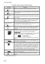
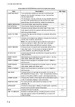
MARKS menu description 

Item Description 

Ref. 

Page 

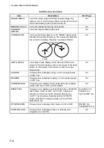
RANGE RINGS 

Turns the range rings on/off and chooses range ring 
interval, 1/4 or 1/2 the range. When turned off, the north 
mark and heading mark are also turned off.   

5-3 

BEARING SCALE 

Turns the electronic bearing scale on/off.   

5-3 

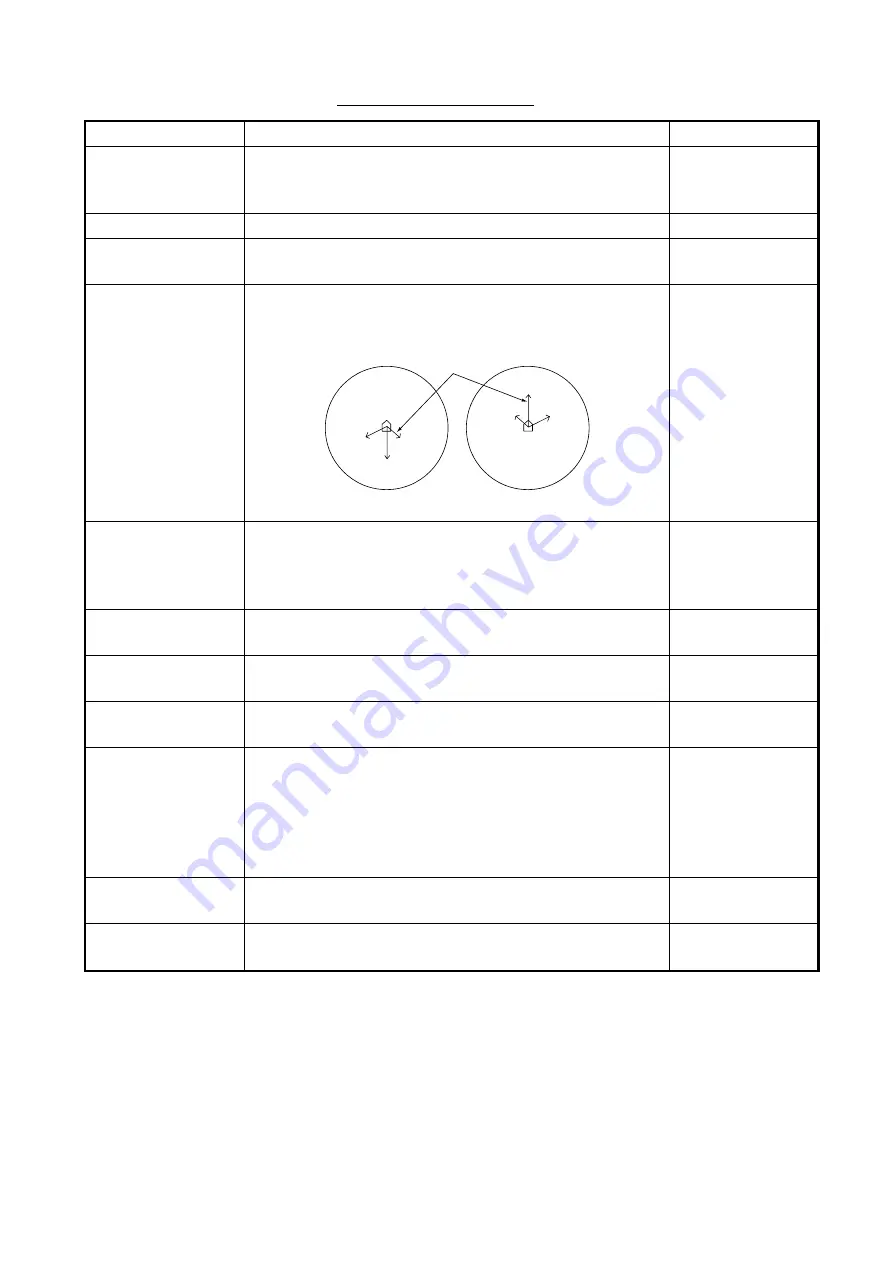
CURRENT 
VECTOR 

Turns the current (tide) mark on/off.   

5-3 

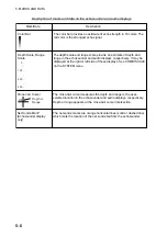
Turns current (tide) data on or off. “FROM” shows what 
direction the current is flowing; “TO” shows the direction 
the current is heading. Requires a current indicator. 

CURRENT DIR 

Current Mark

FROM

TO

3

1

2

3

1

2


5-3 

SHIP’S TRACK 

Turns ship’s track display on/off. 5R and 10R are the 
amount of track to display; that is, the length of the track 
shown on the display is five and ten times the range, 
respectively.  

5-3 

COURSE 

Chooses how to display course, in 32 compass points 
or 360° true. 

5-3 

HEADING 

Chooses how to display heading, in 32 compass points 
or 360° true.


5-2 

CURRENT DATA 

Choose how to display current (tide) data, 32 compass 
points, 360° true, ±180° or 360° relative. 

5-3 

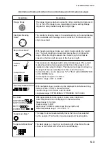
EVENT/FISH 

Choose how to display event and fish marks, 32 CMPS, 
360° TRUE, ±180° or 360°. For “±180°,” starboard 
direction is shown as “xxxS” and port direction as 
“xxxP.” True requires a heading sensor. 32 CMPS 
shows direction in compass points such as N, N/E, 
NNE, NE/N, etc. 

Event MK: 5-5 
Fish MK: 5-4 
Tgt Lock MK: 5-3 

OTHER MARKS 

Chooses how to display other marks, ±180° or 360°. 

R/B MK: 5-4 
Trackball MK: 5-2

POSITION DATA 

Chooses how to display position, in latitude and 
longitude or Loran TDs. 

5-3 

Содержание CSH-5L/CSH-8L

Страница 1: ...COLOR SCANNING SONAR CSH 5L CSH 8L Back ...

Страница 2: ...98 65 4200 FIRST EDITION FIRST EDITION DEC DEC 2002 2002 Printed in Japan Printed in Japan All rights reserved All rights reserved C1 C1 OCT OCT 13 2004 13 2004 Pub No Pub No OME 13190 OME 13190 00080940402 00080940402 00080940402 00080940402 YOTA YOTA CSH 5L 8L CSH 5L 8L 0 0 0 8 0 9 4 0 4 0 2 0 0 0 8 0 9 4 0 4 0 2 OME13190C10 OME13190C10 OME13190C10 OME13190C10 O M E 1 3 1 9 0 C 1 0 O M E 1 3 1 9...

Страница 3: ... result Do not place liquid filled containers on the top of the equipment Fire or electrical shock can result if a liquid spills into the equipment Immediately turn off the power at the switchboard if the equipment is emitting smoke or fire Continued use of the equipment can cause fire or electrical shock Contact a FURUNO agent for service Make sure no rain or water splash leaks into the equipment...

Страница 4: ...the transducer must be replaced yearly The junction between the transducer and main shaft may corrode which can result in loss of the transducer or water leakage iinside the ship WARNING To avoid electrical shock do not remove cover No user serviceable parts inside Name Warning Label 1 Type 86 003 1011 1 Code No 100 236 231 WARNING LABEL A warning label is attached to all units of the system Do no...

Страница 5: ...5 Tilt angle for surface fish 1 13 1 4 6 Suitable tilt angle 1 14 1 5 Finding Range and Bearing to a Target 1 14 1 6 Sonar Menu Overview 1 15 1 6 1 Operating procedure 1 15 1 6 2 Sonar menu description 1 16 2 FINE TUNING THE SONAR PICTURE 2 1 2 1 Eliminating Unwanted Echoes 2 1 2 2 Displaying Surface Fish Clearly 2 2 2 3 Suppressing Bottom Tail 2 2 2 3 1 AGC 2 2 2 3 2 Pulse length 2 3 2 3 3 2ND AG...

Страница 6: ...h 3 10 3 8 3 Programming specific function 3 11 3 8 4 Confirming function key program 3 12 3 9 Suppressing Effects of Pitching and Rolling Stabilizer 3 13 4 ECHOSOUNDER MODE 4 1 4 1 Choosing the Range 4 1 4 2 Adjusting the Gain 4 2 4 3 Picture Advance Speed 4 3 4 4 Measuring Depth 4 3 4 5 Suppressing Interference 4 4 4 6 Suppressing Low Level Noise 4 4 4 7 Erasing Weak Echoes 4 5 4 8 Other Items o...

Страница 7: ...8 3 1 Lubrication points zinc plate 8 2 8 3 2 Manually raising the transducer 8 3 8 4 Fuse Replacement 8 4 8 5 Fan Replacement 8 4 8 6 Troubleshooting 8 5 8 7 Error Messages 8 6 8 8 Diagnostic Tests 8 7 8 8 1 Choosing a diagnostic test 8 7 8 8 2 Description of diagnostic tests 8 8 SPECIFICATIONS SP 1 MENU TREE AP 1 INDEX IN 1 ...

Страница 8: ...ur purposes Thank you for considering and purchasing FURUNO equipment Features The FURUNO CSH 5L and CSH 8L Color Scanning Sonars are full circle electronic scanning sonars that detect and instantaneously display fish schools and underwater conditions in 16 colors Some of the prominent features of the CSH 5L and CSH 8L are as follows Vivid 16 color display assists in recognition of bottom and conc...

Страница 9: ...H 5040 600 mm stroke CSH 5041 400 mm stroke Ship s Mains 100 VAC 115 VAC 200 VAC 220 VAC 240 VAC 1f 50 60Hz DC AC Inverter TR 2451 24 VDC Motion Sensor MS 100 Navaid Current Indicator AD Converter Speed Log E S Interface Remote Controller Speaker Monitor MU 150C etc Max 2 Standard Supply Option User Supply System configuration of CSH 5L ...

Страница 10: ...e Transceiver Unit CSH 8030 Motion Sensor MS 100 Processor Unit CSH 5210 Control Unit CSH 5211 Navaid Current Indicator AD Converter Speed Log E S Interface Remote Controller Speaker Monitor MU 150C etc Max 2 Junction Box CSH 1700 Ship s Mains 100 VAC 115 VAC 200 VAC 220 VAC 240 VAC 1f 50 60Hz System configuration of CSH 8L ...

Страница 11: ...ducer tilt angle Raises the transducer Lowers the transducer Execute assigned program register function key program FISH Inscribes fish mark EVENT Inscribes event mark TARGET LOCK Tracks trackball selected position R B Displays range and bearing marks FISH ALARM Turns fish alarm on off STABILIZER Compensates for affects of ship s pitching and rolling Requires Motion Sensor MS 100 OFF CENTER Shifts...

Страница 12: ...of the tilt range gain and menu functions Hole for hanging TILT Control p Increases tilt angle q Decreases tilt angle RANGE Control p Increases range q Decreases range Chooses menu item in menu operation GAIN Control p Increases gain q Decreases gain Chooses menu option in menu operation Remote controller ...

Страница 13: ...h the screens you see on your display The screen you see depends on your system configuration and equipment settings 1 3 2 Lowering the transducer Set ship s speed under 16 knots and then press the switch The lamp above the switch flashes and lights when the transducer is fully lowered If you press the switch when the speed is over 16 knots and the speed warning is turned on in the SYSTEM menu the...

Страница 14: ...R 7 AGC 2 2ND AGC 1 NOISE LIMITER 3 COLOR CURVE 1 2 3 4 COLOR RESPONSE 1 2 3 4 DELETE COLOR 0 ECHO AVERAGE 1 INT REJECT 1 HOR BEAMWIDTH WIDE NARROW VER BEAMWIDTH WIDE NARROW COLOR 1 2 3 4 ERASE MARKS TRACK SHIP EVENT FISH ALARM LEVEL 9 AUTO TRAIN ON OFF TRAIN SECTOR 10 20 40 60 AUTO TILT ON OFF TILT ANGLE 2 10 4 14 6 20 10 26 TRANSMISSION ON OFF AUDIO VOLUME 10 ASSIGN SETTING F1 KEY F2 KEY F3 KEY ...

Страница 15: ...A SHIP S SPD BR LOG GYRO CURRENT NAV DATA GYRO NAV LOG PULSE 200 400 PORT1 BAUDRATE 19200 9600 4800 2400 PORT1 FORMAT NMEA CIF PORT2 BAUDRATE 19200 9600 4800 2400 PORT2 FORMAT NMEA CIF NAV DATA GPS LC DR ALL COMBI SCALE RIGHT LEFT SUB TEXT INDI OFF ON LANGUAGE ENGLISH JAPANESE ESPANOL DANSK NEDERLND FRANCAIS ITALIANO KOREAN NORSK TEST SINGLE CONTI PANEL COLOR PATTERN SIO ECHO 1 ECHO 2 ECHO 3 ECHO ...

Страница 16: ...n the text window with connection of appropriate sensors Text window Sonar display COMBI 1 Sonar Audio Sonar picture appears on the left and the audio display at the lower right side of the screen This mode is useful analyzing echoes in a desired area To activate the COMBI 1 mode do the following 1 Choose the COMBI 1 mode 2 Use the trackball to place the trackball mark on the bearing desired 3 Pre...

Страница 17: ... Chapter 5 500 W R 1000 T 15 15 G 10 0 S E N N 733 708 189 B 60S Sonar display COMBI 1 display sonar display audio display Text Window For description see Chapter 5 500 W R 1000 T 15 15 G 10 0 S E N N 517 500 134 B 60S R 517 B 60S Range Bearing Marks WATER TEMP 12 4 C 20min 10 0 14 12 10 Range Scale Range and bearing marks data SHIP SPEED 12 4 kt DEPTH 126m SHIP COURSE 246 LAT LON 32 52 150N 132 1...

Страница 18: ...play sonar display echosounder display 1 3 6 Choosing the display range The RANGE control chooses a display range Each time the range is changed the newly selected range appears in large characters for five seconds at the top of the sonar display The current range is always displayed at the top right corner of the sonar display The ranges in meters available are 50 85 100 150 200 250 300 350 400 4...

Страница 19: ...lamp above the switch blinks while the transducer is being retracted Transmission is stopped automatically If you press the switch when the speed is over 16 knots and the speed warning is turned on in the SYSTEM menu the message Max allowable speed for extended transducer is 16 kt Max allowable speed during raising lowering transducer is 16 kt and the audio alarm sounds Press the R B key to silenc...

Страница 20: ...ally tilts the transducer within the tilt range selected on the menu This feature is useful for finding fish school center Automatic tilt becomes inoperative when the target lock feature is made active Disable the target lock feature to resume automatic tilt 1 Press the MENU key to open the menu 2 Operate the RANGE control to choose MENU MODE at the top of the screen 3 Operate the GAIN control to ...

Страница 21: ...00 250 300 350 400 450 500 600 800 1000 1200 1600 10 8 6 2 14 12 10 4 20 16 14 6 26 20 20 10 For example when the RANGE control TILT lever and automatic tilt are set to 1000 m 8 and 2 10 respectively the tilt angle changes at each transmission as follows 8 10 8 6 8 Tilt Angle Auto tilt concept ...

Страница 22: ... This tilt angle receives bottom echoes within the bottom half of the beam Fish echoes astern of the bottom echo are displayed Case 3 Tilt angle 0 to 5 degrees This tilt angle may or may not display returning echoes Fish echoes near the bottom echo are displayed 1 4 3 How to discriminate fish echoes from the bottom The following figure illustrates how two fish schools a and b are displayed on scre...

Страница 23: ... tilt angle is set to 0 degrees the center line is parallel with the sea surface and one half of the emitted sound goes upward toward the sea surface This causes a half of the emitted sound to be reflected back toward the transducer and displayed on the screen as sea surface reflections When the sea is calm since the sound is reflected just like a light hitting a mirror at a narrow incident angle ...

Страница 24: ...le setting 52 m 26 m 15 Depth detection range and tilt angle 1 5 Finding Range and Bearing to a Target Operate the trackball to place the trackball mark on the target you want to measure the range and bearing The slant range horizontal range bearing and depth to the target appear at the upper left corner of the sonar display B Trackball mark î è ê TRACKBALL DATA î Slant range from own ship to trac...

Страница 25: ...NAR to display the SONAR menu SONAR MENU RANGE CTRL U D GAIN CTRL L R MENU MODE SONAR SOUNDER MARKS SYSTEM DISPLAY MODE COMBI 1 NORM COMBI 2 TX OUTPUT 8 PULSE LENGTH 8 TX CYCLE 10 TVG NEAR 6 TVG FAR 7 AGC 2 2ND AGC 1 NOISE LIMITER 3 COLOR CURVE 1 2 3 4 COLOR RESPONSE 1 2 3 4 DELETE COLOR 0 ECHO AVERAGE 1 INT REJECT 1 HOR BEAMWIDTH WIDE NARROW VER BEAMWIDTH WIDE NARROW COLOR 1 2 3 4 ERASE MARKS TRA...

Страница 26: ...em Description Ref page DISPLAY MODE Chooses the display mode among COMBI 1 NORM Audio NORM Sonar and COMBI 2 NORM Echosounder 1 6 TX OUTPUT Adjusts transmitter power 2 4 PULSE LENGTH Chooses pulse length 2 3 TX CYCLE Removes interference caused by other sonars operating nearby 2 6 TVG NEAR Adjusts receiving gain within 300 m 2 1 TVG FAR Adjusts receiver gain beyond 300 m 2 1 AGC Automatically red...

Страница 27: ...r narrow 2 7 COLOR Chooses display colors for the sonar and audio displays among four choices Choose a display color to match your environment or fishing objective ERASE MARKS Chooses the mark type to erase collectively from track own ship event and fish For track 10 of the oldest track is erased 3 9 ALARM LEVEL Sets echo strength level which triggers the fish alarm The lower the setting the weake...

Страница 28: ...1 OPERATIONAL OVERVIEW 1 18 This page intentionally left blank ...

Страница 29: ...imilar intensities irrespective of the ranges to them The CSH 5L CSH 8L incorporates two TVG functions NEAR and FAR and they mainly compensate for propagation loss on short and long ranges respectively centered at the ranges shown below NEAR FAR 300 m How TVG works The TVG is also used to suppress unwanted echoes and noise which appear in a certain range area on the screen such as sea surface refl...

Страница 30: ...ddition to the TVG adjustment described earlier adjust AGC on the SONAR menu Normally set it between 0 and 3 2 3 Suppressing Bottom Tail As noted earlier fish schools echoes located near the bottom are sometimes difficult to detect because you have to discriminate them from the bottom reflections AGC PULSE LENGTH and 2ND AGC in the SONAR menu if used properly decrease the tail of bottom reflection...

Страница 31: ... longer the pulse length 6 Press the MENU key to close the menu 2 3 3 2ND AGC While it is ideal to suppress bottom echoes with the AGC alone there are some fishing grounds where this is not possible The high power sonar has the advantage of long range detection but this can also be a disadvantage since weaker echoes may be hidden in strong unwanted echoes such as the bottom If you cannot suppress ...

Страница 32: ... becomes clearer when the output power is reduced rather than when the gain is decreased as illustrated below 1 Press the MENU key The last used menu appears 2 Use the RANGE control to choose MENU MODE at the top of the screen 3 Use the GAIN control to choose SONAR to display the SONAR menu 4 Use the RANGE control to choose TX OUTPUT 5 Use the GAIN control to set TX output The higher the setting s...

Страница 33: ...ng random noise and sea surface reflections in rough sea conditions Set the interference rejector so that noise is just eliminated Do not use an unnecessarily high setting since small wanted echoes may also be rejected 1 Press the MENU key 2 Use the RANGE control to choose MENU MODE at the top of the screen 3 Use the GAIN control to choose SONAR to display the SONAR menu 4 Use the RANGE control to...

Страница 34: ... Use the RANGE control to choose MENU MODE at the top of the screen 3 Use the GAIN control to choose SONAR to display the SONAR menu 4 Use the RANGE control to choose TX CYCLE 5 Use the GAIN control to set TX cycle The setting range is 0 10 and the higher the figure the longer the TX cycle 6 Press the MENU key to close the menu Note When the sonar is used in shallow waters with the range set betwe...

Страница 35: ... the MENU key to open the menu 2 Use the RANGE control to choose MENU MODE at the top of the screen 3 Use the GAIN control to choose SONAR 4 Use the RANGE control to choose DELETE COLOR 5 Use the GAIN control to choose setting The setting range is 0 10 and the higher the number the stronger the echo that will be erased 6 Press the MENU key to close the menu 2 8 Echo Averaging You may adjust echo a...

Страница 36: ...2 FINE TUNING THE SONAR PICTURE 2 8 This page intentionally left blank ...

Страница 37: ...onar display Note that target lock is automatically cancelled when the echo moves 1 5 times the range in use Target Lock Data Target Lock Mark NNE Relative bearing to target B 650 Horizontal range from own ship to target 153 Depth of target Target lock bearing mark Relative bearing format may be selected with OTHER MARKS on the MARKS menu Any value which exceeds 9999 is displayed with four asteris...

Страница 38: ...gle For example if a ship moves from position A to position D the target lock works between positions A and B The tilt angle is fixed between positions B and C is 55 however calculation continues internally Target lock is restarted after position C Depth 55 55 A B C D Target lock and tilt angle ...

Страница 39: ... when the R B key is pressed the range and bearing marks and range and bearing marks data are erased 2 Press the R B key The bearing mark appears on the bearing selected with the trackball mark Listen to echoes through the loudspeaker You may adjust the volume of the loudspeaker with AUDIO VOLUME on the SONAR menu 3 To change aural coverage area do the following a Press the MENU key to open the me...

Страница 40: ... paints a fan shaped alarm zone The audio alarm will be released when an echo enters the alarm zone Starting Point Ending Point Alarm Area Fish alarm zone Note 1 There must be at least three degrees difference between the starting and end points to get a fan shaped alarm zone as shown in a and b below Otherwise a 360 alarm zone is painted as in c and d More than 3 a b c d Within 3 Fish alarm zones...

Страница 41: ...e latest fish mark and the speed and course of the fish school are shown at the bottom right corner of the sonar display Latest Fish Mark Latest Fish Mark FIsh Mark Data 2nd Latest Fish Mark Wait 1 2 minutes C E S Course S 2 3kt Speed 787 Horizontal range from own ship to fish mark 153 Depth X Past Fish Mark Max 8 Place trackball mark on fish echo and press the FISH key Place trackball mark on fis...

Страница 42: ...ctively see paragraph 3 7 1 Operate the trackball to place the trackball mark on the fish mark you want to delete The color of the fish mark changes from white to red if the trackball mark is correctly placed 2 Press the DELETE MARK key to delete the fish mark 3 5 Relocating Fish School for Easy Observation 1 Operate the trackball to place the trackball mark on the position where you want to reloc...

Страница 43: ...ure from direction of mark How to use the event mark Entering an event mark 1 Operate the trackball to place the trackball mark where you want to place an event mark latest event mark 2 Press the EVENT key The horizontal range depth and bearing to the event mark appear at the bottom left corner of the sonar display Event mark position is calculated from ship s speed and heading data and it moves o...

Страница 44: ...s 3 6 2 Entering an own ship position mark Operate the trackball to place the trackball mark on the own ship mark and press the EVENT key to inscribe an own ship position mark 10 own ship position marks may be entered When this amount is exceeded the oldest own ship position mark is automatically erased 3 6 3 Deleting an event mark You may delete specific event mark as follows 1 Operate the trackb...

Страница 45: ... 3 Use the GAIN control to choose SONAR 4 Use the RANGE control to choose ERASE MARKS 5 Use the GAIN control to choose item to delete TRACK SHIP EVENT or FISH TRACK The oldest 10 of the ship s track is erased with each press of the EVENT key SHIP The oldest own ship mark is deleted with each press of the EVENT key EVENT FISH All corresponding marks are erased when the EVENT key is pressed 6 Press ...

Страница 46: ...s set according to function key program or a dialog box appears in case of shortcut operation For shortcut operation go to step 2 The illustration below shows the ERASE MARKS dialog box 2 Press the same function key again within five seconds to set value or choose option Be sure to press the function key within five seconds the dialog box is automatically erased after five seconds In case of the S...

Страница 47: ...CURVE 1 COLOR CURVE 4 COLOR CURVE 3 COLOR RESPONSE 3 COLOR RESPONSE 1 COLOR RESPONSE 3 3 8 3 Programming specific function You may program a function key with a menu item from the SONAR or SOUNDER menu to use as shortcut Most items are available except TRANSMISSION ASSIGN SETTING and ASSIGN MENU from the SONAR menu and DRAFT from the SOUNDER menu Locked items shown in red are available however the...

Страница 48: ...NU key to open the menu 2 Use the RANGE control to choose MENU MODE 3 Use the GAIN control to choose SONAR 4 Use the RANGE control to choose ASSIGN MENU The current programs are shown at the top of the menu F1 F1 KEY F2 F2 KEY F3 TVG NEAR F4 TVG FAR Function key assignment confirmation screen 5 Press the MENU key to close the menu ...

Страница 49: ... stabilizer activated How the stabilizer works 1 Operate the trackball to place the trackball mark on the bearing where you want the stabilizer the picture 2 Press the STABILIZER key The stabilizer mark a dashed line extending from the screen center to the edge of the effective diameter of the sonar display appears on the bearing selected and STAB appears at the top right corner of the sonar displ...

Страница 50: ...can be manually set in the range of 0 55 however pitching and rolling are compensated within the 20 in the tilt angle range of 0 to 55 Note 2 If the target lock is activated while the stabilizer is on the bearing set for target lock will be used with the stabilizer as well and the stabilizer mark is erased When the target lock is turned off the bearing set before target lock was turned on is used ...

Страница 51: ...he basic range can be thought of as providing a window into the water column and range shifting as moving the window to the desired depth Display Shift Display range and shift concept Note Select the Range and Shift to the same setting as the echo sounder connected This setting does not affect the original echo sounder setting 1 Press the MENU key to open the menu 2 Use the RANGE control to choose...

Страница 52: ...range 0 1000 meters 8 Press the MENU key to close the menu 4 2 Adjusting the Gain You may adjust the display level of the echo sounder picture as below the gain of the echo sounder itself cannot be adjusted from the sonar Note Set the gain to the same setting as the echosounder connected This setting does not affect the original echosounder setting 1 Press the MENU key to open the menu 2 Use the R...

Страница 53: ...s the EVENT key 6 Use the GAIN control to adjust advance speed desired The fractions in the dialog box are one line produced per number of transmissions For example 1 2 displays one scan line per two transmissions 7 Press the MENU key to close the menu 4 4 Measuring Depth You can measure depth to the cross hair cursor as follows 1 Use the trackball to place the trackball mark inside the echosounde...

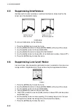
Страница 54: ...f no interference exists choose OFF 6 Press the MENU key to close the menu 4 6 Suppressing Low Level Noise Low level noise often caused by sediments in water is painted on the screen as a large number of light blue dots These echoes may be suppressed as below Clutter 1 Press the MENU key to open the menu 2 Use the RANGE control to choose MENU MODE at the top of the screen 3 Use the GAIN control to...

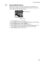
Страница 55: ...trength as below Weak reflections Weak echoes 1 Press the MENU key to open the menu 2 Use the RANGE control to choose MENU MODE at the top of the screen 3 Use the GAIN control to choose SOUNDER 4 Use the RANGE control to choose DELETE COLOR 5 Use the GAIN control to choose setting desired The setting range is 0 10 and the higher the setting the stronger the echo that will be erased 6 Press the MEN...

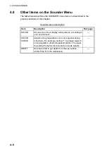
Страница 56: ... Ref page COLOR Choose one of four display color patterns according to your environment COLOR CURVE Adjusts echo presentation color curve against strong reflections For example setting 1 averages weak to strong signals to obtain a balanced picture The larger the setting the better the resolution on weak signals DRAFT Set ship s draft to get depth from the sea surface rather than from the transduce...

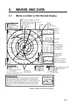
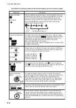
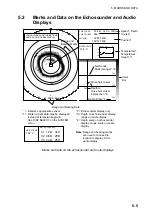
Страница 57: ...E S 10 5kt Fish Mark Data B 557 149 SW W Target Lock Data Range Depth Bearing 2 North Mark Range Shown several seconds when range is changed TX Off Stabilizer On Speed Course Position Depth Current Data current speed and direction for 3 layers Temperature Temperature Graph Range Tilt Angle Auto Tilt value Gain Function Key Number Freeze condition for testing Requires appropriate sensor S E N N 1 E...

Страница 58: ...in parentheses Accordingly both are equal when target lock is on In automatic tilt the upper indication shows the tilt angle set by the TILT lever and the lower indication the instantaneous tilt angle at which the sonar actually works Relative bearing Bearing is shown in 360 or 180 indication system relative to ship s heading In the latter case B isindicated as follows on the port side on the star...

Страница 59: ...rs 1 3 selected on the current indicator The tidal current speed is shown by the length of the line extending from the center of the mark Current direction can be shown as to or from with CURRENT DIR on the MARKS menu Current speed range 0 0 to 9 9 kt Direction range 180 or 0 359 C1 kt C2 kt C3 kt Nav Data SHIP SPEED kt SHIP COURSE With appropriate sensors speed course water depth and water temper...

Страница 60: ...n the screen by pressing the FISH key Ten fish marks can be displayed Each time the key is pressed the fish marks change on the screen as follows 1st press of FISH key 2nd press of FISH key 3rd press of FISH key 4th press of FISH key Fish movement from the latest fish mark to the 2nd latest fish mark is shown by horizontal range depth speed S and course C at the lower right corner of the screen Th...

Страница 61: ...ross hair Cursor Net Sonde Mark orange 2 SONAR MARKS AND INDICATIONS SAME AS ON NORMAL DISPLAY Speed Depth Course Position Temperature Temperature Graph 1 R 552 B 60S Range and Bearing Data Range and Bearing Marks Note Range and bearing marks are used to choose the location to display in the audio display 2 Echosounder display only 3 Depth on echosounder display range on audio display 4 Depth scal...

Страница 62: ...d audio displays respectively It may be displayed at the right or left side of those displays See COMBI SCALE on the SYSTEM menu Net Sonde Mark Echosounder display only The net sonde marks are orange horizontal lines solid or dashed line which mark the location of the net sonde fed from the echosounder Cross hair Cursor The cross hair cursor measures the depth and range to the user selected locati...

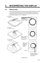
Страница 63: ... net from being damaged by a reef or a shipwreck A Flat bottom Tilt angle 10 to 15 B Flat bottom Tilt angle 20 or more C Sloping bottom Tilt angle 20 or more Bottom Shallow bottom is displayed in a strong color and with a short tail Bottom is displayed narrower and in stronger colors when compared to A Decreased tilt angle Only half of vertical beam width captures the bottom The deeper sloping bot...

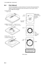
Страница 64: ...ngle 30 or more Fish echo which appears before bottom can be detected Tilt angle 0 to 20 Fish echo which appears together with or after bottom can be detected Bottom Fish school Sea surface reflections Fish school Bottom echo not displayed because of decreased tilt angle Sea surface reflections are present Fish school Large midwater fish school is present Bottom To search bottom fish use a narrow ...

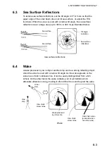
Страница 65: ...ion Sea surface reflections Tilt 0 Tilt 5 6 Sea surface reflections 6 4 Wake A wake produced by own ship or another ship can be a strong reflecting object when the sonar is used with a narrow tilt angle As the wake appears on the screen as a thick continuous line it can be easily distinguished from a fish school On the other hand the wake contains a lot of air bubbles which attenuate ultrasonic en...

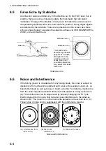
Страница 66: ...e when the sidelobe points ver tically Also poor soundome projection may result in a similar false echo Sidelobe echo 6 6 Noise and Interference If the fishing ground is crowded with many fishing boats the sonar is subject to interference from ultrasonic equipment such as an echo sounder sonar etc on board other boats as well as those on board own ship For instance interference from the sonar oper...

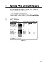
Страница 67: ... control to choose SYSTEM or MARKS as appropriate 7 1 MARKS Menu MARKS MENU RANGE CTRL U D GAIN CTRL L R MENU MODE SONAR SOUNDER MARKS SYSTEM RANGE RINGS 1 4R 1 2R OFF BEARING SCALE ON OFF CURRENT VECTOR ON OFF CURRENT DIR TO FROM SHIP S TRACK 10R 5R OFF COURSE 32CMPS 360TRUE HEADING 32CMPS 360TRUE OFF CURRENT DATA 32CMPS 360TRUE 180 360 EVENT FISH 32CMPS 360TRUE 180 360 OTHER MARKS 180 360 POSITI...

Страница 68: ...track to display that is the length of the track shown on the display is five and ten times the range respectively 5 3 COURSE Chooses how to display course in 32 compass points or 360 true 5 3 HEADING Chooses how to display heading in 32 compass points or 360 true 5 2 CURRENT DATA Choose how to display current tide data 32 compass points 360 true 180 or 360 relative 5 3 EVENT FISH Choose how to di...

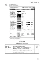
Страница 69: ...NMEA CIF NAV DATA GPS LC DR ALL COMBI SCALE RIGHT LEFT SUB TEXT INDI OFF ON LANGUAGE ENGLISH JAPANESE ESPANOL DANSK NEDERLND FRANCAIS ITALIANO KOREAN NORSK TEST SINGLE CONTI PANEL COLOR PATTERN SIO ECHO 1 ECHO 2 ECHO 3 ECHO 4 SET TO DEFAULT EXECUTE PRESS MENU KEY TO EXIT SYSTEM menu Description of SYSTEM menu Item Description Ref Page DIMMER Adjust control panel backlighting 1 5 DISP SELECT Choose...

Страница 70: ...rce of speed and course data with which to draw ship s track The choices are log gyrocompass current indicator nav data and gyro nav data LOG PULSE Chooses log pulse mile specification of speed log 200 or 400 pulses mile PORT1 BAUD RATE Sets baud rate of equipment connected to port 1 among 2400 4800 9600 and 19200 bps PORT1 FORMAT Sets format of equipment connected to port 1 NMEA or CIF Furuno POR...

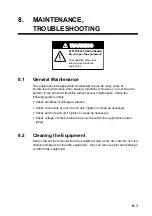
Страница 71: ...utmost of its ability without proper maintenance Check the following points monthly Check all cables If damaged replace Check connectors at rear of each unit Tighten or clean as necessary Check earth of each unit Tighten or clean as necessary Check voltage of ship s mains to be sure it is within the equipment s power rating 8 2 Cleaning the Equipment Dust or dirt can be removed from the equipment ...

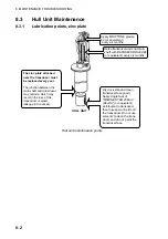
Страница 72: ...ransducer face yearly Apply single coat of MARINE STAR 20 Mod Red N or equivalent anti foulant to transducer face to keep marine life off the transducer Do not use solvents to clean the trans ducer and do not paint the transducer face The zinc plate attached near the transducer must be replaced every year The junction between the main shaft and transducer may corrode which may result in the loss o...

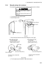
Страница 73: ... shaft gear Motor gear Screw M4 X 8 4 pcs OFF ON Hull unit 3 Mount the hand crank onto the screw shaft gear or motor gear a Mounting hand crank on screw shaft gear Requires greater force but smaller number of turns b Mounting hand crank on motor gear Requires less force but greater number of turns Hand crank Fix with screw Use cover fixing screw Fix with screw Use cover fixing screw Screw shaft ge...

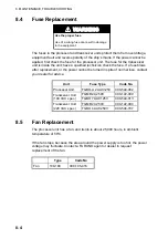
Страница 74: ...blows after replacement or the power cannot be turned in spite of normal fuse contact your dealer for advice Unit Fuse Type Code No Processor Unit FGBO A 2A AC125V 000 549 062 FGMB 2A 250V 000 122 000 Transceiver Unit 100 VAC spec FGBO 7A AC125V 000 549 013 FGMB 2A 250V 000 122 000 Transceiver Unit 220 VAC spec FGBO 4A AC250V 000 546 707 8 5 Fan Replacement The processor unit has a fan and its lif...

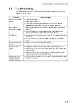
Страница 75: ...on period is longer so ship s pitching and rolling are apt to affect detection of echo Weak echo Output power set to minimum Set TX OUTPUT SONAR menu to maximum Excessive TVG Readjust TVG NEAR and FAR on the SONAR menu Somewhat strange color Brilliance too low Adjust display brilliance Picture contains noise Equipment not grounded properly Check equipment ground Power cable is too close to the sig...

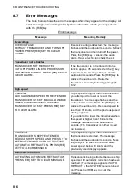
Страница 76: ...16 KT MAX ALLOWABLE SPEED DURING RAISING LOWERING TRANSDUCER IS 16 KT PRESS R B KEY TO CLEAR ALARM Ship s speed is higher than 16 knots when you attempted to lower or retract the transducer The message flashes and the audio alarm sounds Press the R B key to silence the audio alarm Reduced speed to less than 16 knots and the previously used display appears If you attempt to lower the transducer whe...

Страница 77: ...MENU MODE SONAR SOUNDER MARKS SYSTEM DIMMER 10 DISP SELECT TEMP CURRENT HEADING ADJ 0 AUTO RETRACT OFF OFF 5 16kt OFF SPEED MESSAGE ON OFF EXT KP SYNC OFF ON AUTO TRAIN SPD LOW HIGH AUTO TILT SPD LOW HIGH UNIT METERS FEET FATHOMS PA BRA SHIP S SPD BR LOG GYRO CURRENT NAV DATA GYRO NAV LOG PULSE 200 400 PORT1 BAUDRATE 19200 9600 4800 2400 PORT1 FORMAT NMEA CIF PORT2 BAUDRATE 19200 9600 4800 2400 PO...

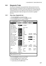
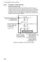
Страница 78: ...on CONTI TEST MAIN 0 1050729 XX XX F FF ROM OK RAM OK VRAM OK EEPROM P W OK TRX 1050 XX XX 1050 XX XX FF FF ROM OK RAM OK DROM OK KEY 0 1050730 XX XX F ROM OK RAM OK XX XX Program Version No 742 CSH 5L 55 kHz 68 kHz 735 CSH 8L 85 kHz 736 CSH 8L 107 kHz 733 CSH 5L 55 kHz 734 CSH 5L 68 kHz9 735 CSH 8L 85 kHz 736 CSH 8L 107 kHz F DIP SW setting Control unit s program version no and results of ROM and...

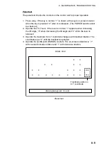
Страница 79: ...he lever is normal 1 appears when increasing the tilt angle 2 when decreasing the tilt angle and 0 when the lever is released 3 Operate the trackball Its X Y coordinate changes with trackball rotation The coordinates are 0 until the trackball is operated 4 Operate the GAIN and RANGE controls The on screen indication is 1 with counterclockwise rotation and 1 with clockwise rotation Trackball positi...

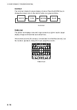
Страница 80: ...n and blue WHITE RED GREEN BLUE Color test Pattern test The pattern test displays concentric rings overlaid on a grid to test for proper display of rings and horizontal and vertical lines If the test shows error for example no horizontal or vertical lines shown see the monitor s operator s manual for how to adjust the monitor PATTERN TEST PRESS MENU KEY TO EXIT Pattern test ...

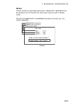
Страница 81: ... processor unit The result for the CN A1 port is shown as OK or NG No Good The test for the NMEA1 CIF1 and NMEA2 CIF2 ports is for factory use The result is always NG SIO TEST TRX OK PORT1 NG PORT2 NG NMEA2 CIF2 port check NMEA1 CIF1 port check CN A1 port check PRESS MENU KEY TO EXIT PORT 1 2 FACTORY USE ONLY SIO test ...

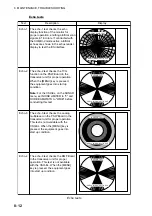
Страница 82: ...s the TVG function on the PSW Board in the transceiver unit for proper operation When the MENU key is pressed the equipment goes into start up condition Note For the CSH 8L on the SONAR menu set NOISE LIMITER to 0 and HOR BEAMWIDTH to WIDE before conducting this test Echo 3 The echo 3 test checks the analog multiplexer on the PSW Board in the transceiver unit for proper operation This test is not ...

Страница 83: ...rk Horizontal range depth first event marked depth bearing Bearing Range Mark Bearing range Own Ship s Position Latitude longitude LOP Navigation Data Ship s speed bearing depth water temperature Current Data Current speed and direction 1 5 Unit Meter feet fathom P B 1 6 Features Interference rejecter Afterglow Noise limiter Numeric indication Automatic tilt scanning Over voltage Warning Unretract...

Страница 84: ... Under certain circumstances a target fish school may not be detected due to its nature or because of sea conditions ever if it is located within the display range 2 6 Pulse length 0 5 to 20 ms interlocked with range can be changed in 11 steps 2 7 Pulse Repetition Rate PRR 0 25 to 4 4 s interlocked with range can be changed in 11 steps External synchronized transmission keying 2 8 Audio Search Met...

Страница 85: ... D sub15P female 4 5 CIF Data Input Location Ship s Speed Bearing Current data 1 Layer Water depth Water temperature Multiple layer current data 5 POWER SUPPLY 5 1 Processor Unit 100 115 200 220 240 VAC 1 phase 50 60 Hz CSH 5L 100 115 200 VAC 4 0A 200 220 240 VAC 2 0A CSH 8L 100 115 200 VAC 4 5A 200 220 240 VAC 2 2A 5 2 Inverter Required for 24 VDC 6 ENVIRONMENTAL CONDITION 6 1 Ambient Temperature...

Страница 86: ...This page is intentionally left blank ...

Страница 87: ...HOR BEAMWIDTH WIDE NARROW VER BEAMWIDTH WIDE NARROW COLOR 1 2 3 4 ERASE MARKS TRACK SHIP EVENT FISH ALARM LEVEL 0 14 9 AUTO TRAIN ON OFF TRAIN SECTOR 10 20 40 60 AUTO TILT ON OFF TILT ANGLE 2 10 4 14 6 20 10 26 TRANSMISSION ON OFF AUDIO VOLUME 0 10 10 ASSIGN SETTING F1 KEY F2 KEY F3 KEY F4 KEY ASSIGN MENU EXECUTE MENU key SONAR selected from MENU MODE Sounder menu COLOR 1 2 3 4 RANGE 20 320 160 m ...

Страница 88: ...MODE DIMMER 0 10 10 DISP SELECT TEMP CURRENT HEADING ADJ 0 359 0 AUTO RETRACT OFF 5 16 kt SPEED MESSAGE ON OFF EXT KP SYNC OFF ON AUTO TRAIN SPD LOW HIGH AUTO TILT SPD LOW HIGH UNIT METERS FEET FATHOMS PA BRA SHIP S SPD BR LOG GYRO CURRENT NAV DATA GYRO NAV LOG PULSE 200 400 PORT1 BAUDRATE 19200 9600 4800 2400 PORT1 FORMAT NMEA CIF PORT2 BAUDRATE 19200 9600 4800 2400 PORT2 FORMAT NMEA CIF NAV DATA...

Страница 89: ...ontinuous test 8 8 echo tests 8 12 panel test 8 9 pattern test 8 10 single test 8 8 SIO test 8 11 DIMMER 1 5 Display mode 1 6 Draft sonar 4 6 E Echo average 2 7 Echo tests 8 12 Error messages 8 6 EVENT key 3 7 Event marks deleting 3 8 deleting all 3 9 entering 3 7 F Fan replacement 8 4 Fish alarm 3 4 FISH ALARM key 3 4 FISH key 3 5 FISH marks deleting all 3 9 deleting individual 3 6 entering 3 5 F...

Отзывы: