background image

1. OPERATION

13

8. Use 

T

 to choose Span (or Radius for Arrival) 

and press the 

ENTER

 key.

9. Use 

S

 or 

T

 to set the range of depth, tem-

perature, speed or distance as appropriate.
To shorten the alarm range marker use 

T

and to lengthen use 

S

.

10.For the bottom alarm, temperature alarm, 

speed alarm or arrival alarm, press the 

ENTER

 key to finish, and then go to step 13. 

For a fish alarm, press the 

ENTER

 key and 

go to step 11.

11.Use 

T

 to choose Fish Level and press the 

ENTER

 key.

Fish Level setting box

12.Use 

S

 or 

T

 to choose the echo strength 

level which will trigger a fish alarm and press 
the 

ENTER

 key.

Weak:

 Light-blue or stronger echoes

Medium:

 Yellow or stronger echoes

Strong:

 Red and reddish brown echoes

13.Press the 

MENU/ESC

 key twice to close the 

window.

Note1:

 To disable an alarm, choose Off at step 

4 in the above procedure.

Note2:

 The audio and visual alarms are 

released against the last-violated alarm when 
multiple alarms are active.

1.17 FUNC Key

The 

FUNC

 key provides for instant display of a 

user-defined options window chosen with 
FUNC Key on the Key menu. Nine items are 
available: Pic. Advance (default), Shift, Interfer-
ence, Clutter, Color Erase, White Line, White 
Marker, WPT List and Bottom Zone. For details 
about registration, see section 2.2. Use the 

FUNC

 key as follows.

1. Press the 

FUNC

 key to open the setting

window registered; for example, Pic. 
Advance setting window.

2. Use 

FUNC

 key, 

S

 or 

T

 to adjust the setting 

and press the 

ENTER

 key.

1.18 Waypoints

Waypoints may be used to:

• Record the position of an important echo as 

waypoint. 20 points may be registered.

• Output a waypoint position to a plotter to 

mark position on its screen.

• Find range, bearing and time-to-go to a 

location (waypoint).

Note:

 Requires latitude and longitude position 

from a navigator.

1.18.1   Registering a waypoint

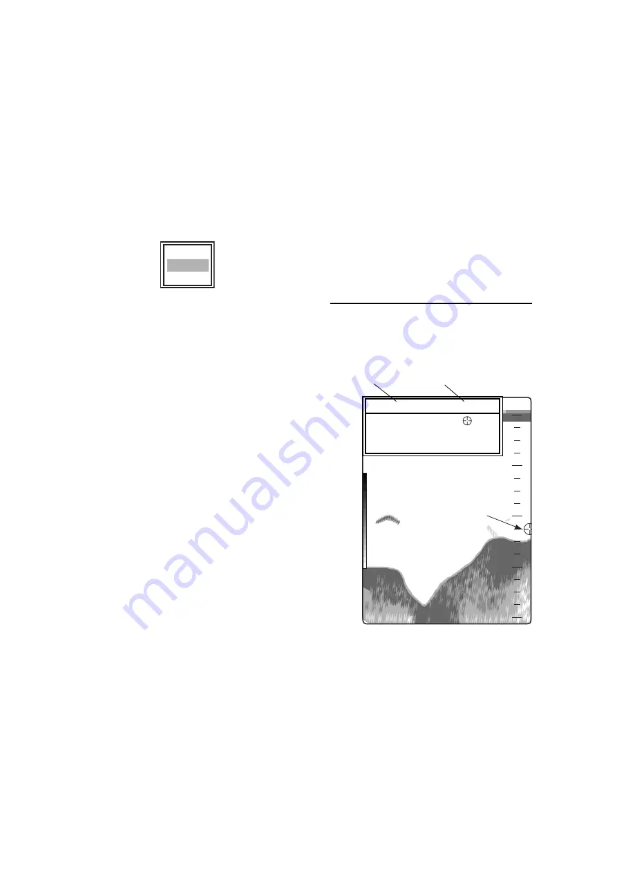
Registering a waypoint on the screen

1. Press the 

MARK

 key.

The cursor appears along with waypoint 
entry instructions. To enter a waypoint to the 
current own ship's position, go to step 3.

Cursor

Note:

 If there is no position data the message 

"No position data!" appears. Check the navi-
gator.

2. Press the 

TrackPad

 to set the cursor where 

desired.
Picture advancement is stopped until step 3 
is completed, and the instruction window is 
integrated into the data box.

Weak
Medium
Strong

Cursor

49.6

m

20

40

60

80

0

45.0m              50.0

°

F

S

 / 

T

 / 

W

 / 

X

      :  Move       cursor

[ENTER] / [MARK] :  Set
[MENU]                              :  Cancel

Depth and temperature of cursor position

Содержание Color LCD Sounder FCV-620/585

Страница 1: ......

Страница 2: ... may not match the screens you see on your display The screen you see depends on your system configuration and equipment set tings This manual is intended for use by native speakers of English FURUNO will assume no responsibility for the damage caused by improper use or modification of the equipment or claims of loss of profit by a third party Please carefully read and follow the operation install...

Страница 3: ...ith the transducer out of water The transducer may be damaged The picture is not refreshed when picture advancement is stopped Maneuvering the vessel in this condition may result in a dangerous situation Use the proper gain setting Incorrect gain may produce wrong depth indication possibly resulting in a dangerous situation CAUTION WARNING To avoid electrical shock do not remove cover No user serv...

Страница 4: ...ed with improper installation Use the specified power cable Use of other power cable may result in fire CAUTION Do not install the equipment where air bubbles and noise are present Performance will be affected The following are guidelines for handling of the transducer cable Keep fuels and oils away from the cable Locate it in a safe place Do no paint the cable The sheath of the cable is made of c...

Страница 5: ... 2 1 Displaying System Sub Menu 20 2 2 Range Menu 20 2 3 Key Menu 20 2 4 Lang Menu 20 2 5 Units Menu 21 2 6 Calib Menu 21 2 7 Demo Menu 21 3 MAINTENANCE TROUBLE SHOOTING 22 3 1 Maintenance 22 3 2 Cleaning the Display Unit 22 3 3 Transducer Maintenance 22 3 4 Replacing the Fuse 22 3 5 Battery Voltage Alert 22 3 6 Troubleshooting 23 3 7 Diagnostics 23 3 8 Test Pattern 24 3 9 Memory Clear 24 4 INSTAL...

Страница 6: ...hieving our purposes Thank you for considering and purchasing FURUNOequipment Features The FURUNO FCV 620 585 is a dual frequency 50 kHz and 200 kHz Color LCD Sounder Comprised of a display unit and a transducer the FCV 620 displays underwater conditions on a 5 6 inch color LCD and the FCV 585 on an 8 4 inch color LCD The main features of the FCV 620 585 are Bright color LCD gives excellent readab...

Страница 7: ... temperature sensor Transducer 520 5PSD 520 5MSD 525 5PWD 525ST MSD 525ST PWD Standard Option Power supply 12 24 VDC Local Supply Water temperature speed sensor ST 02MSB ST 02PSB Water temperature sensor T 02MSB T 02MTB T 03MSB GPS Navigator or Water temperature sensor Transducer 520 5PSD 520 5MSD 525 5PWD 525ST MSD 525ST PWD Matching Box MB 1100 For connection to 1 kW transducer 50B 6 50B 6B 200B...

Страница 8: ...cs M4 SUS304 000 864 126 Spring washer 4 pcs M4 SUS304 000 864 256 Threaded rod 4 pcs M4x50 SUS304 000 162 679 10 MJ cable cap 1 pc 02 154 1221 1 100 329 441 Filter cleaner 1 pc 02 155 1082 1 100 332 651 10 Spare Parts SP02 05001 Fuse 2 pcs FGBO A 125V 2A 000 155 849 10 Template C22 00502 000 156 349 1 For flush mounting Operator s Guide MLG 23740 000 156 373 1 Operator s Manual OME 23740 000 156 ...

Страница 9: ...8 577 1 For flush mounting Operator s Guide MLG 23740 000 156 373 1 Operator s Manual OME 23740 000 156 346 1 Name Type Code No Qty Remarks Conversion Cable 02S4147 000 141 082 1 For water temperature and spd temp sensors Water Temperature Speed Sensor ST 02MSB 000 137 986 1 Thru hull type ST 02PSB 000 137 987 Water Temperature T 02MTB 000 040 026 1 Transom mount w 8 m cable T 02MSB 000 040 040 Th...

Страница 10: ...ation 2 STWX TrackPad Moves cursor on the menu Adjusts settings Moves VRM Variable Range Marker by using S or T except for nav mode 3 ENTER Saves settings 4 RANGE Opens display range setting window 5 MARK Records the position of an important echo as waypoint Outputs latitude and longitude position to a plotter 6 FUNC Opens user defined window 7 GAIN Push Opens automatic gain setting window Rotatin...

Страница 11: ...er selecting Brill by using S or T you may also use W or X to adjust brilliance 3 To adjust contrast after selecting Contrast by using S or T use W or X only for FCV 620 0 is the lowest and 9 is the highest 4 Press the ENTER key to save the setting and close the window Note When the power is reapplied after turning off the equipment with minimum brilliance min imum brilliance will be set after the...

Страница 12: ...ottom zoom and marker zoom The default mode is bottom lock To change a mode see page 16 Bottom lock display The bottom lock display provides a normal pic ture on the right half of the screen and a 10 30 feet default 15 feet wide layer in contact with the bottom is expanded onto the left half of the screen This mode is useful for detecting bottom fish Bottom lock display Note1 To adjust the range o...

Страница 13: ... left of the screen Data other than depth requires appro priate sensor Two nav data displays are available Nav Data 1 or Nav Data 2 and you may choose which to use on the Display menu The default settings are as follows Nav Data 1 Two data display SPEED STW WIND Nav Data 2 Four data display DEPTH TEMPERATURE TRIP METER ODOMETER You can display between two and four items in a nav data display and c...

Страница 14: ...ishing and Cruising mode so that the bottom is displayed as reddish brown Gain offset lets you override automatic gain adjustment 1 Press the GAIN knob to open the Auto Gain setting window Auto Gain setting window 2 Press the GAIN knob again to choose Fishing or Cruising You may also use S or T to choose the mode Fishing This mode clearly displays weaker echoes and is for searching fish schools G ...

Страница 15: ...e VRM 1 8 Menu Operating Procedure The FCV 620 585 have five menus Sounder Display Alarm Data and System Below is the basic menu operating procedure 1 Press the MENU ESC key to open the menu Menu 2 Use S or T to choose the menu or sub menu desired The cursor yellow shows current selection The items in the right window change with menu selected 3 Press the ENTER key The cursor yellow shifts to the ...

Страница 16: ... to choose Sounder and press the ENTER key 3 Use S or T to choose Shift and press the ENTER key Shift setting window 4 Use S or T to choose an amount of shift desired and press the ENTER key 5 Press the MENU ESC key twice to close the window Note The echo may be lost if the amount of shift is greater than actual depth 1 10 Choosing Picture Advance Speed The picture advance speed determines how qui...

Страница 17: ...ference setting window 4 Use S or T to choose the degree of sup pression desired and press the ENTER key Off Turn off interference rejector Low Medium High High provides the greatest degree of suppression and Low is the smallest Auto Interference is suppressed automati cally Note Turn off the interference rejector when no interference exists so as not to miss echoes from small fish 5 Press the MEN...

Страница 18: ... the degree of suppression 5 Press the MENU ESC key twice to close the window 1 13 Erasing Weak Echoes Sediment in the water or reflections from plankton may be painted on the display in low intensity tones Appearance of weak echoes These weak echoes may be erased by using the Color Erase This function erases weaker echoes sequentially to show only strong echoes and clear up the picture 1 Press th...

Страница 19: ...r off Also you can show or hide the fish size and the depth value For details about the Fish Symbols see the information which follows the procedures in this section Note The fish size found by this sounder is intended for reference purposes it is not an accurate measurement of fish length Fish Symbols 1 Press the MENU ESC key to open the menu 2 Use S or T to choose Display and press the ENTER key...

Страница 20: ...value and the fish caught you can compensate it on the Calib menu see sec tion 2 6 When Fish Symbols or Fish Info are enabled 50 kHz and 200 kHz beams are transmitted alternately even if a single fre quency mode is in use To reduce error the detection area should be 2 to 100 meters from the surface With the inside hull transducer signal attenuation is different between 50 kHz and 200 kHz Therefore...

Страница 21: ...water temperature or arrival distance is out side the range set 5 Press the ENTER key For Arrival Alarm go to step 8 6 Use T to choose From and press the ENTER key Depth setting window Temperature Speed setting box 7 Use S or T to set starting depth tempera ture or speed as appropriate and press the ENTER key For Bottom and Fish Normal the starting depth is the range from the trans ducer and for F...

Страница 22: ...dvance default Shift Interfer ence Clutter Color Erase White Line White Marker WPT List and Bottom Zone For details about registration see section 2 2 Use the FUNC key as follows 1 Press the FUNC key to open the setting window registered for example Pic Advance setting window 2 Use FUNC key S or T to adjust the setting and press the ENTER key 1 18 Waypoints Waypoints may be used to Record the posi...

Страница 23: ...t step a and b to set the name desired and press the ENTER key 6 Press the MENU ESC key to close the window Registering a waypoint by L L 1 Press the MENU ESC key to open the menu 2 Use S or T to choose Data and press the ENTER key Data menu 3 Use S or T to choose WPT List and press the ENTER key WPT List window 4 Use S or T to choose an empty waypoint and press the ENTER key The Waypoint setting ...

Страница 24: ...ndow 1 19 Setting Up Nav Data Displays The user may arrange the nav data displays as desired 1 19 1 Nav data displays 1 Rotate the MODE knob to choose NAV1 or NAV2 Nav Data setting window Note The setting window disappears if there is no operation for about ten seconds In this case press the TrackPad to re display the window 2 Use S or T to choose a data display window desired 3 Use W or X to choo...

Страница 25: ...ottom Zone Set the area where to display the bottom echo when selecting Auto mode on the RANGE key 1 Choose Bottom Zone in the Sounder menu and press the ENTER key XTE MARINA XTE 0 20nm 27 3nm Rng PORT SPEED SOG SPEED STW WIND True WPT MARINA COMPASS True HEADING True SOG Speed over ground STW Speed relative to water 1234ft DEPTH 2345 6789N 12345 6789E POSITION 12 3kt SPEED SOG 12 3kt SPEED STW 12...

Страница 26: ...n the depth The gain is low at short distance and getting back with increasing distance High provides the greatest degree of gain reduction against short range echoes Note that this func tion is operative when manual is selected on the GAIN knob Smoothing Smoothes echo presentation when enabled Adjust the setting when echoes appear spotty TX Power Interference may appear on the screen when an echo...

Страница 27: ...the dividing line and press the ENTER key Battery Turn the battery voltage indication appears at the top right corner on the screen on or off When on it replaces the picture advance speed indication Color Bar Turn the color bar on or off Palette Change the background color of the screen in five colors white blue black gray and night Colors Choose the number of colors to use 8 16 or 64 Header Info ...

Страница 28: ...ation of the true wind and the boat s movement True The speed and direction in relation to ship s heading of the wind felt or measured when stationary Trip Source Choose speed source for the trip distance indication Off Own speed sensor connected to the FCV 620 585 or NMEA speed data from external equipment Temp Source Choose source of water temper ature input Off Own temperature sensor con nected...

Страница 29: ... Key menu FUNC Key Register the item for instant dis play of a user defined options window Nine items are available Pic Advance default Shift Interference Clutter Color Erase White Line White Marker WPT List and Bottom Zone You may program the FUNC key to display the options window of your choice 1 Long press the FUNC key to open the FUNC Key setting window 2 Use S or T to choose function item des...

Страница 30: ...ndication is 2 higher than actual water temperature enter 2 The setting range is 20 0 to 20 0 F Speed STW If the speed indication has error you can correct it here For example if the speed indication is 10 lower than actual speed enter 10 The setting range is 50 to 50 Fish Size Compensate for wrongful indica tion of fish size setting range 80 to 100 Water Type Choose the water type with which to u...

Страница 31: ... No 000 155 849 10 in the power cable pro tect the system from reverse polarity of the power supply and equipment fault If a fuse blows find the cause before replacing it Using the wrong fuse will damage the unit and void the warranty 3 5 Battery Voltage Alert A battery icon appears when the battery voltage is too high or too low Checking Item Action Transducer cable Check cable for damage Power c...

Страница 32: ...range scale appears battery voltage fuse power supply power cable no echo appears but the fixed range scale appears if display advance speed is not set to Stop transducer plug transducer cable echo appears but no zero line if range shifting is set to 0 sensitivity is low gain setting if air bubbles or marine life is not clinging to the transducer face if sediments are not present in the water if t...

Страница 33: ...Test and press the ENTER key 4 Press any key except MENU ESC key to start the test The entire screen changes as below with each press of any key except MENU ESC key After crosshatch screen the Tests menu appears LCD test pattern 5 Press the MENU ESC key twice to close the window 3 9 Memory Clear The memory can be cleared to start afresh with default menu settings except for lan guage setting 1 Pre...

Страница 34: ...crews 5x25 supplied 3 Loosely screw knob into the bracket assembly 4 Set the display unit to the bracket assembly 5 Adjust the angle of the display unit and then tighten the knob to fix the display unit Note When loosening the knob to adjust the angle of the display do not decline the unit 90 degree backward The cable connector may be damaged if it contacts the bracket 6 Attach the hard cover to t...

Страница 35: ...ocated in a position where water flow is the smoothest Noise from the propellers also adversely affects performance and the transducer should not be mounted nearby The lifting strakes are notorious for creating acoustic noise and these must be avoided by keeping the transducer inboard of them The transducer must always remain sub merged even when the boat is rolling pitching or up on a plane at hi...

Страница 36: ...t amount of high quality caulking compound to the top surface of the transducer around the threads of the stuffing tube and inside the mounting hole and fairing blocks if used to ensure water tight mounting 5 Mount the transducer and fairing blocks and tighten the locking nuts Be sure that the transducer is properly oriented and its working face is parallel to the waterline Note Do not over stress...

Страница 37: ...ng screws 3 Adjust the transducer position so the trans ducer faces right to the bottom If necessary to improve water flow and minimize air bubbles staying on the trans ducer face incline the transducer about 5 at the rear This may require a certain amount of experimentation for fine tuning at high cruising speeds 4 Fill the gap between the wedge front of the transducer and transom with epoxy mate...

Страница 38: ...unted 2 Clean the transducer face again to remove scourings 3 Warm the silicone sealant to 40 C before usage to soften it Coat the transducer face and mounting location with silicone sealant Coating transducer face with silicone sealant 4 Press the transducer firmly down on the hull and gently twist it back and forth to remove any air which may be trapped in the silicone sealant Checking the insta...

Страница 39: ...oggles Dust mask Electric drill Drill bit for Bracket holes 4mm 23 or 9 64 Fiberglass hull chamfer bit preferred 6mm or 1 4 Transom hole 19mm or 3 4 optional Cable clamp holes 3mm or 1 8 Screwdrivers Straight edge Marine sealant Pencil Zip ties Water based antifouling paint mandatory in salt water Mounting location To ensure the best performance the sensor must be submerged in aeration free and tu...

Страница 40: ...ket and sensor to the transom to determine if the plastic shim is needed 5 Using the three 10 x 1 1 4 self tapping screws temporarily screw the bracket to the hull DO NOT tighten the screws com pletely at this time Follow the step 1 4 in Attaching the sensor to the bracket before proceeding with Adjusting Adjusting 1 Using a straight edge sight the underside of the sensor relative to the underside...

Страница 41: ...ed in the transom above the waterline Never cut the cable or remote the connector this will void the warranty Always wear safety goggles and a dust mask 1 If a hole must be drilled choose a location well above the waterline Check for obstructions such as trim tabs pumps or wiring inside the hull Mark the location with a pencil Drill a hole through the tran som using a 19 mm or 3 4 bit to accom mod...

Страница 42: ...ace apart from equipment gen erating heat Choose a place in the forward direction viewing from the drain hole to allow for cir culation of cooling water 1 Dry dock the boat 2 Make a hole of approx 51 mm diameter in the mounting location 3 Unfasten locknut and remove the sensor section 4 Apply high grade sealant to the flange of the sensor 5 Pass the sensor casing through the hole 6 Face the notch ...

Страница 43: ... guide with high quality sealant and pass gasket washer and locknut onto holder guide in that order and then tighten the locknut 3 Set the sensor holder to the holder guide from inside the boat and then tighten the locknut 4 Launch the boat to check for water leakage around the sensor Mounting T 03MSB 4 8 Wiring Connect the power data cable assy KON 004 02M 2 m supplied to the 12 24 VDC NMEA port ...

Страница 44: ...d sensor to the XDR port with the optional con version cable Type 02S4147 as shown below Connection of conversion cable 02S4147 Optional transducer The optional matching box Type MB 1100 Code No 000 041 353 is required to con nect the optional transducers 50B 6 50B 6B 200B 5S 50 200 1T Matching box MB 1100 cover removed Connector Color Remarks 1 TD A WHT IEC61162 1 NMEA0183 2 TD B BLU 3 RD A YEL I...

Страница 45: ...pressure MDA Water temperature MTW Wind speed and angle true apparent MWV Available with connection of optional sen sors navaid Part Type Code No Qty Matching Box MB 1100 000 041 000 1 Crimp on Lug FV1 25 3 red 000 538 113 6 Cord Lock NC 1 000 516 650 1 Input data sentences Sentence Meaning BWC Bearing and distance to waypoint GGA Global positioning system GPS fix data GLL Geographic position lati...

Страница 46: ... in Europe and Japan During the devel opmental phase the reliability and availability of the WAAS signal cannot be guaranteed Therefore any position data should be veri fied against other sources to confirm reli ability This function is available only when In Out is selected at NMEA Port TLL Output Output the position specified by MARK key to the plotter connected Off Does not output latitude long...

Страница 47: ... Temp Graph Off Narrow Wide Window Size Battery Off On Color Bar Off On Palette White Blue Black Gray Night Colors 8 16 64 Header Info Off On Nav Data1 Nav Data2 Fish Info Off Fish Size Depth Fish Symbols Off Solid Striped Alarm Bottom Off On From 0 2500 ft 0 ft Span 1 2500 ft 10 ft Fish Normal Off On From 0 2500 ft 0 ft Span 1 2500 ft 10 ft Fish B L Off On From 0 0 30 0 ft 0 0 ft Span 0 1 30 0 ft...

Страница 48: ...7 7 2500 ft 600 ft Range 8 7 2500 ft 1000 ft Zoom Range 7 2500 ft 15 ft B L Range 10 30 ft 15 ft Key FUNC Key Pic Advance Shift Interference Clutter Color Erase White Line White Marker WPT List Bottom Zone Key Beep Off On Lang Language English OTHERS Units Depth m ft fa pb HR Temp C F Fish Size inch cm Speed kt km h mph Wind kt km h mph m s Distance nm km sm NMEA NMEA0183 Ver 1 5 Ver 2 0 Ver 3 0 N...

Страница 49: ...ttom lock Bottom zoom Marker zoom 2 4 Basic Range Basic Range Unit 1 2 3 4 5 6 7 8 Setting Range m 5 10 20 40 80 150 200 300 2 to 800 ft 15 30 60 120 200 400 600 1 000 7 to 2 500 fa 3 5 10 20 40 80 100 150 2 to 400 pb 3 5 10 20 50 100 150 200 2 to 450 HR 4 8 15 30 50 100 150 200 2 to 500 Japanese unit of depth measurement 2 5 Range Shift 0 to 800 m 0 to 2 500 ft 0 to 400 fa 0 to 450 pb 0 to 500 HR...

Страница 50: ...r temperature MTW Wind speed and angle true apparent MWV 3 2 Output Data Sentences IEC61162 1 NMEA0183 Ver 1 5 2 0 3 0 interval 2 s DBT DPT MTW VHW TLL by key operating External data required 4 POWER SUPPLY 4 1 FCV 620 12 24 VDC 0 8 0 4 A 4 2 FCV 585 12 24 VDC 1 0 0 5 A 5 ENVIRONMENTAL CONDITION 5 1 Ambient Temperature 15 C to 50 C 5 2 Relative Humidity 93 at 40 C 5 3 Waterproofing and IP55 Dust P...

Страница 51: ...䎼䎑䎃䎫䏄䏗䏄䏌 䎼䎑䎃䎫䏄䏗䏄䏌 Ha tai 電子署名者 Hatai DN cn Hatai c JP 日本 o Seigi ou Joho email yoshitoshi hatai furuno co jp 日付 2006 03 02 11 23 20 09 00 D 1 ...

Страница 52: ...䎼䎑 䎫䏄䏗䏄䏌 Hatai 電子署名者 Hatai DN cn Hatai c JP 日本 o Seigi ou Joho email yoshitoshi hatai furuno co jp 日付 2006 03 09 17 17 27 09 00 䎼䎑䎃䎫䏄䏗䏄䏌 D 2 ...

Страница 53: ...D 3 ...

Страница 54: ...DR SHIELD SPD0V ST SHIELD 9 8 10 2 3 6 5 4 1 MJ A6SRMD 1 TEMP SPEED SENSOR 水温 船速センサー TRANSDUCER 送受波器 02S4147 0 2m 2 MJ A10SRMD 2 3 6 5 4 1 または OR T 02MSB T 02MTB T 03MSB TEMP SENSOR 水温センサー 2 選択 SELECT FCV 585 only FCV 585のみ 3 3 3 GND IV 1 25sq 1 10 9 8 7 6 5 4 2 3 XDR MJ A10SPF 520 5MSD 525ST MSD 525ST PWD 送受波器 水温 船速センサー付 または OR 520 5PSD 525 5PWD TRANSDUCER 送受波器 TRANSDUCER W TEMP SPEED SENSOR 選択 S...

Страница 55: ......

Страница 56: ...dition 1996 11 Clauses 10 2 and 10 3 IEC 60945 Fourth edition 2002 08 Clauses 9 2 9 3 10 3 10 4 10 5 10 8 and 10 9 title and or number and date of issue of the standard s or other normative document s For assessment see EMC Test Report FLI 12 05 053 of 14 November 2005 prepared by Furuno Labotech International Co Ltd This declaration is issued according to the Council Directive of 3 May 1989 on th...

Отзывы: