38
5.7 Tilt Code Disk Alignment
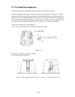
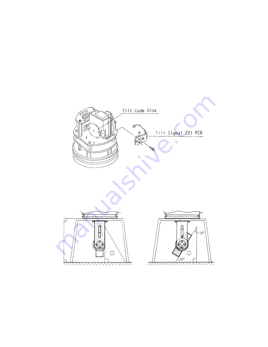
When the tilt gear bos is reinstalled, alignment of the tilt code disk is required.
The tilt code disk has three slits; two narrow slits for 30° signal and one wide slit +8° and 93°
signals. Two narrow slits should be located in the center of photo sensors on tilt signal (1) and
(2) boards. Note that improper alignment causes the error message “TILT NG” and stoppage of
whole operation; if the mechanical stopper works 8° or 93° signal is produced or if the
two sensors are not activated simultaneously at 30° tilt, the error message is generated.
1) Remove the tilt signal (2) pcb 06P0156.
2) Loosen two socket set-screws on the shaft of the tilt code disk.
Figure 5.13
3) Place the soumdome assembly vertically.
4) Tilt the transducer exactly 30°
Figure 5.14 Placing Soundome Vertically Figure 5.15 Tilting Transducer 30
°
Содержание CH-270
Страница 1: ...COLOR SEARCHLIGHT SONAR CH 270...
Страница 13: ...10 58 59 6 6 DRV 06P0154 Hull Unit XDR Slip ring Figure 2 1 Signal Flow in Transmitter...
Страница 14: ...11 Hull unit XDR Slip ring 6 6 59 58 Figure 2 2 Signal Flow in Receiver...
Страница 19: ...16 Figure 2 5 TRANSCEIVER UNIT CPU J2 3 4 3 4 5 6 J10 5 6 7 8 CR16 U17 U34 191 R104 R105...
Страница 23: ...20 DRV Board 06P0154...
Страница 33: ...30 Figure 4 11 Raise Lower Unit 06P0147 F1 4A F2 12V 4V 24V 3A S1 S3 R3 S2 R4 TRAIN Board 06P0154...
Страница 54: ......
Страница 55: ......
Страница 64: ......
Страница 65: ......
Страница 66: ......
Страница 67: ......
Страница 68: ......
Страница 69: ......
Страница 70: ......
Страница 71: ......
Страница 72: ......
Страница 73: ......
Страница 74: ......
Страница 75: ......
Страница 76: ......
Страница 77: ......
Страница 78: ......
Страница 79: ......
Страница 80: ......
Страница 81: ......
Страница 82: ......
Страница 83: ......
Страница 84: ......
Страница 85: ......
Страница 86: ......
Страница 87: ......
Страница 88: ......

