

C16AK0009 REV.1
SLIMBOX-V, INDOOR ENCLOSURE-24F
ISSUE DATE 8/5/2016
pg. 8
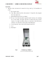
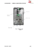
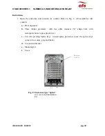
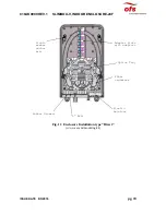
2.
Follow the enclosure installation steps from the paragraph entitled “Wall installation
instructions (paragraph 2)
3.
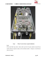
Cut the middle entry port rubber grommet following the molded in notch until you reach
the center of the molded hole. Thread drop cable through the he just created opening. Use
the cable aramid yarn, “L” bracket and cable ties to restrain the cable.
4.
Splice provided SC/APC 900 µm pigtails with the drop cable fibers. Store the splice
protectors in the pivoting splice trays. Use the slack management spool and the splice trays
to manage fiber extra length.
5.
Plug the spliced pigtail SC/APC ends into designated SC/APC adapters located in the
adapter bracket to mate with the splitter input fiber.
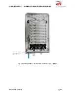
6.
Use left and right entry port for drop cables installation. Choose the grommet hole to
match the cable size. Cut the rubber grommet following the molded in notch until you
reach the center of the molded hole. Thread the MPO connectorized drop cable through
the just created opening.
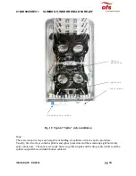
7.
Attach the aramid yarn to the retaining” L” bracket with the provided plastic ties.
8.
Record the connection information on the destination sheet and insert the sheet into the
document holder located on the inside wall of the cover
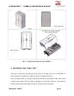
9.
Assemble the cover to the base