Funk Amateur FA-VA5 Скачать руководство пользователя страница 32

30 •  BX-245

© Box 73 Amateurfunkservice GmbH 2019

does  not  concern  the  FA-VA5  and  can

therefore be confirmed with 

ok

. The same

applies to the following warning.

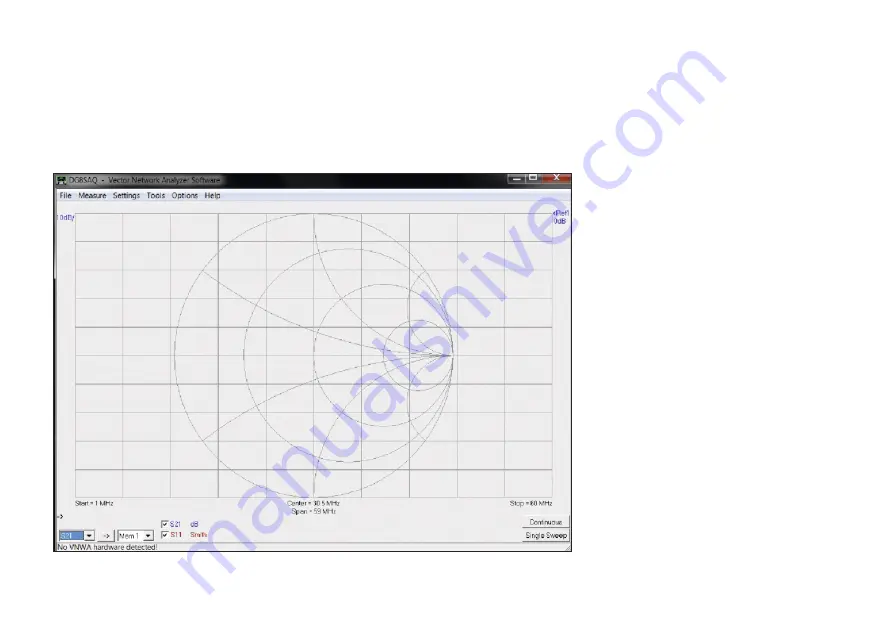
The VNWA entry screen is initially quite

simple and uncluttered (Fig. 56). The soft-

ware at the bottom left of the window will

report that no VNWA hardware has been

detected. If the existing grid is not clearly

visible (depending on the standard win-

dow colour of the Windows version), the

background colour can be changed via the

menu item 

Settings

Diagrams

Dis-

play

Grid Options

and thus adapted to

your own taste.

n

Connecting the FA-VA5 
to VNWA: 

The FA-VA5 must be able to communicate

with  the  PC  before  you  can  use 

VNWA

software. To do this, put the analyzer in

USB mode. If this has not already been

changed by the user in the FA-VA5 menu

(go to 

Setup

USB Auto Mode

), the ana-

lyzer  will  automatically  switch  to  USB

mode  when  the  USB  cable  is  inserted.

Otherwise, the USB mode can be manual-

ly selected at any time via the Operating

menu. Once this has been done, in the VN-

WA Application under 

Options

Select

Instruments

Add to /remove, from the

displayed list select

DG5MK Antenna

Analyzer

Now the FA-VA5 has been added to the

list of selectable devices. The actual selec-

tion is then made using 

Options

Select

Instrument

DG5MK Antenna Analyz-

er

. Next VNWA still needs to know which

COM port was detected by the Windows

Device Manager. This is done in the VN-

WA Application under 

Options

Setup

.

A new  window  opens  and  the  correct

COM port is selected from the list in box

Port. A successful connection to the FA-

VA5 is acknowledged on the top right with

the word connected in green and a status

line in blue indicating the firmware ver-

sion of the analyzer (Fig. 57). This com-

Fig. 56: VNWA Startup screen after installation of VNWA Software

Содержание FA-VA5

Страница 1: ...Assembly and Operating Manual Kit for an easy to use vector antenna analyzer for use in the frequency range 10 kHz to 600 MHz Vector Antenna Analyzer FA VA5 Ver E 1 3 2019 08 06...

Страница 2: ......

Страница 3: ...Vectorial measurement means that unlike a scalar instrument not only the SWR is measured and displayed but also the value of the impedance including the signed imaginary part The so called SOL Short...

Страница 4: ...3 4 0 dBm 3rd harmonic P5 8 3 dBm 5th harmonic f 200 MHz RL 50 P1 4 5 dBm 1st harmonic fundamental P3 7 2 dBm 3rd harmonic P5 15 3 dBm 5th harmonic Current consumption 38 mA 65 mA at 1 MHz 47 mA 85 mA...

Страница 5: ...e board It should rest flush on the board with no space underneath its actuating knob must be horizontal with re spect to the board surface Fig 3 The easiest way to achieve this is if only one of the...

Страница 6: ...he left side of the housing If necessary the accuracy of fit can now be corrected relatively easily If everything is correct then continue and solder all 16 solder pads of the USB Board to the main bo...

Страница 7: ...connections of the 20 pin con tact strip Fig 6 It is recommended to use a suitable base under the display during soldering in order to fix it flush on the lighting unit Caution The protective film on...

Страница 8: ...with the display board as the 20 pin strip is prone to bend slightly Place the display together with the socket strips on the board Next the four card board strips are inserted Fig 8 then turn over w...

Страница 9: ...st and final Assembly Before installing the board into the hous ing a short functional test is required First fit the three plastic caps on the push but tons and fit the previously assembled dis play...

Страница 10: ...pen when transmitting with the anten na connected in close proximity of the VA5 Likewise static charges must be kept away from the test socket Isolated antenna structures must therefore be dis charged...

Страница 11: ...nce relative to known component values either directly or through the reflec tion coefficient after calibration has been performed All other values e g SWR are mathematically calculated from the measu...

Страница 12: ...frequency dependent error During the master calibration the actual input impedance is automatically mea sured at intervals of 100 kHz or 1 MHz for all three reflection defined cases and the calculate...

Страница 13: ...on can be enabled or disabled and is accessed via Operating mode Setup SOL Selecting Off sets the No Calibration mode Current calibration This can be performed for single frequen cy mode Fig 13 as wel...

Страница 14: ...e Master Calibration will be invalid Note The Master Calibration process takes about 20 25 minutes but can be cancelled if desired In this case however inconsistent reference values may arise so this...

Страница 15: ...R Impedance or Reflection coefficient measurement at current frequency SWR measurement with sound signal current calibration Multifrequency modes SWR Impedance or Reflection coefficient measurement wi...

Страница 16: ...e g for antenna tuning As the SWR decreases the faster the beeps will sound making it easy to hear when the lowest SWR is measured The actual measuring frequency can be set using the three buttons Use...

Страница 17: ...he use of master calibration current calibration via the menu item SOL 5 Band is also possible for this mode Fig 24 Prior to perform ing Current calibration however the five required measuring frequen...

Страница 18: ...section Setup In contrast to modes and pressing a button does not trigger a new measuring cycle but merely displays the changed marker position including the correspond ing measured value The measure...

Страница 19: ...ring run Con tinuous Sweep run This is automatically restarted by the Analyzer again and again Changes in the measured values are there fore relatively quickly visible The disad vantage however is a h...

Страница 20: ...een views and or Da taset information can be selected here All measurement modes allow you to save a screen snapshot of the current display view To do this briefly press the left and right buttons at...

Страница 21: ...Data from Memory Screen in opera ting mode Fig 35 The corresponding display memory can be selected with the and buttons Fig 37 Unused memory locations are displayed empty The left button allows you to...

Страница 22: ...of the frequency value digit to be changed and if necessary correct this with the plus or minus button When jumping from the last digit left to the first digit right 1 Hz the abbreviation for Enter ap...

Страница 23: ...ration Callsign Personalization option by entering the call sign Backlight Mode Setup of the display backlight options Display Update cycle Defines the repetition rate of the measurements USB Auto Mod...

Страница 24: ...encies This item has already been covered in the section Basic Calibration SOL Compen sation Callsign If you want to personalize your FA VA5 you can use this menu item e g to save your call sign maxim...

Страница 25: ...ller is clocked at a lower frequency Alonger dis play duration therefore meets a lower power requirement Fig 46 USB Auto Mode After connecting to a Personal Computer PC via USB cable the FA VA5 will b...

Страница 26: ...correction Thereafter the frequency of the Analyzer output signal should be exactly equal to the set frequency It should be noted however that this frequency correction is usually not required for ant...

Страница 27: ...kHz etc SWR minimum for multi frequency measurements With SWR multi frequency measurements the marker can be automatically set to dis play minimum SWR and this value can be transferred to the single...

Страница 28: ...time a firmware update is done Reset When this option is selected and con firmed all parameters are reset to the fac tory settings and the master calibration and all stored display views are deleted...

Страница 29: ...eaningful results are obtained Measuring impedance and SWR of an antenna at one frequency The antenna is connected directly to the base or via a cable to the analyzer You will need to decide if the wh...

Страница 30: ...onances oc cur at wavelengths of 1 4 3 4 etc of the electrical length of the cable High Z impedance When the cable end is shorted the reso nances occur at wavelengths of 1 2 1 3 2 etc of the electrica...

Страница 31: ...powered up via the USB connection The operating system does not automatically find the correct driver for Silicon Labs on all tested ver sions of Windows 7 or later It is therefore recommended to inst...

Страница 32: ...u go to Setup USB Auto Mode the ana lyzer will automatically switch to USB mode when the USB cable is inserted Otherwise the USB mode can be manual ly selected at any time via the Operating menu Once...

Страница 33: ...aset records Import After clicking on the second tab in Fig 58 a window appears as shown in Fig 59 Here analogous to the local menu of the FA VA5 the 16 available Dataset records are listed with their...

Страница 34: ...display is pro cessed and is displayed in the main win dow of the program a popup info window confirms the read in process Fig 62 For the familiar SWR display the following quick fix solution is avail...

Страница 35: ...this case in blue In the example in Fig 63 the frequency marker is at 6 29 MHz where an SWR val ue s 4 46 was measured The described procedure sounds a bit complicated due to its detailed description...

Страница 36: ...clicking on one of the frequencies dis played below the bottom of the Grid left Start middle centre or right Stop fre quency The frequency window Input will open and allows you to enter the start and...

Страница 37: ...onnect the Short cal ibration element to the FA VA5 After its connection and confirmation a measure ment cycle starts the circle turns green with red M in the middle Similarly the calibration for Open...

Страница 38: ...p is meaningful for matting of the selected output traces In the main window Fig 66 colour coded top left shows the scale for each trace On the right side there is again colour coded the specification...

Страница 39: ...52 MHz of the DUT the imaginary part of the reflection coefficient is zero here The VSWR at this frequency is s 1 45 We wish you great success and fun in set ting up and operating the FA VA5Antenna An...

Страница 40: ...a wave is transmitted from the input to the output S21 or from the output back to the input S12 Furthermore the proportion of a reflected wave at the input S11 or at the output S22 can be measured The...

Страница 41: ...2 for the display Main PCB SMD 1 components fitted Enclosure 1 consists of upper and lower shell Rubber foot 4 Cylinder screw M3 4 4 for mounting the Main PCB Countersunk screw M3 4 4 for assembling E...

Страница 42: ...fully soldered OPEN element ready for use SHORT is ready for use Slide the centre pin with the wire until it clicks into place Remove the wire Slide the centre pin with the soldered wire until it clic...

Страница 43: ......

Страница 44: ...rt problems to support funkamateur de Order no BX 245 When disposing of this product please observe the regulations for the handling of electronic waste Electronic devices batteries and components do...

Отзывы: