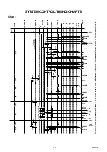
background image

1-7-8

T6550MTI

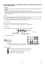
Mechanical Malfunction determination

1) REEL Malfunction detection

Countermeasure for REEL and CAPSTAN motor
rotation malfunction (Except CASSETTE LOAD-
ING function)

After the Malfunction detection with REEL/CAP-
STAN sensor, the unit shall switch over to STOP
(B) and be REEL Mechanical Malfunction.

a) If the T-REEL pulse is not impressed after a lapse

of 7 sec. at SP, 14 sec. at LP, or more in the REEL
Rotation Mode like PLAY/REC, FS/RS Mode, and
the T-REEL or S-REEL pulse is not impress after a
lapse of 4 sec. or more in REEL Rotation Mode of
FF/REW, it shall be assumed to stop the rotation
and switch over to STOP (B) position, then
POWER be turned OFF and the unit be REEL
Mechanical Malfunction. (T-REEL and S-REEL for
the models on S-REEL and only T-REEL for other
models)

b) If the C-FG pulse is not impressed for a lapse of 1

sec. or more during the CAPSTAN MOTOR rota-
tion, it shall be MOTOR Rotation Malfunction
(REEL Malfunction).

2) DRUM Malfunction detection

Detect the DRUM rotation at the D-FG input termi-
nal. 

If the variation of D-FG input level is not detected
for a lapse of 1 sec. or more when D-CONT is "H",
it shall be assumed to be Rotation Malfunction and
be DRUM Malfunction. 

When detect Drum Malfunction, POWER shall be
turned OFF after the unit switches over to STOP
(B) Mode.

3) Countermeasure for TAPE LOADING Malfunction

Detect the Malfunction with the LOADING Switch.

a) TAPE LOADING Malfunction

If LD-SW does not go to the established position
after a lapse of 7 sec. or more from TAPE LOAD-
ING or TAPE UNLOADING start, the LOADING
function shall immediately be stopped and POWER
be turned OFF, and inform the Timer about the
LOADING Mechanical Malfunction.

b) LD-SW Position Malfunction at each mode

When the unit operates at each mode, even if the
LD-SW position changes from the established one
in its mode, it keeps the function according to its
mode.

4) Countermeasure for CASSETTE LOADING Mal-

function

a) CASSETTE IN operating Malfunction

If LD-SW does not go to SB position after a lapse
of 5 sec. or more from the CASSETTE insertion
start, the unit starts the CASSETTE OUT opera-
tion. 

After switch over to CASSETTE OUT operation and
then a laps of 5 sec. or more from the CASSETTE
OUT operation start, if LD-SW does not go to the
EJ position or if START Sensor and END Sensor
does not turn "ON" at the EJ position, the unit
starts again to insert CASSETTE.

(However in S-INH state, the START/END Sensor
shall be disabled).

b) CASSETTE OUT operating Malfunction

After a lapse of 5 sec. or more from CASSETTE
OUT operation start, if LD-SW does not go to the
EJ position or if START Sensor and END Sensor
does not turn "ON" at the EJ position, the unit
starts to insert CASSETTE.

(However in S-INH state, the START/END Sensor
shall be disabled).

When the unit switches over to CASSETTE inser-
tion at CASSETTE IN or CASSETTE OUT Mal-
function, if LD-SW does not go to the SB position
after a lapse of 5 sec. or more from CASSETTE
insertion start, the function shall immediately be
stopped and POWER be turned OFF, and the unit
be CASSETTE LOADING Malfunction.

c) When POWER is turned ON, if the CL position or

GC position cannot be detected after 5 sec. LD-
REV operation and 5 sec. LD-FWD operation, the
function shall immediately be stopped and POWER
be turned OFF, and the unit be CASSETTE LOAD-
ING Malfunction.

d) When POWER is turned ON without CASSETTE

(EJ position) and LD-SW is monitored all the time,
if the CL or GC position is detected continuously for
1 sec. or more, the POWER shall be turned OFF
and the unit be CASSETTE LOADING Malfunction.

Countermeasure for Mechanical
Malfunction

If the unit detects Mechanical Malfunction, turn the
POWER OFF. If the unit is Mechanical Malfunction,
Key input except POWER key shall be disabled and
CASSETTE insertion disabled. When POWER Key is
entered, the POWER is turned ON and the unit
switches over the EJECT Mode. (Return with POWER
ON)

Содержание TVCR-2104

Страница 1: ...Mechanism I Disassembly Assembly of Mechanism I Alignment Procedures of Mechanism I Deck Exploded Views I Deck Parts List 21 COLOR TV VCR COMBINATION TVCR 2104 PAL SECAM PAL This service manual is fo...

Страница 2: ...Adjustment Instructions 1 6 1 Block Diagrams 1 7 1 Mechanical Trouble Indicator 1 7 7 Schematic Diagrams CBA s and Test Points 1 8 1 Waveforms 1 9 1 Wiring Diagram 1 10 1 System Control Timing Charts...

Страница 3: ...ity Horizontal 15 Vertical 10 3 High Voltage kV 25 Description Condition Unit Nominal Limit 1 Misconvergence Center m m 0 6 Corner m m 2 5 Side m m 1 8 2 Contrast Control Range dB 6 3 Brightness APL 1...

Страница 4: ...0 4 Audio Freq Response 20dB Ref 1kHz 200Hz R P 6kHz R P dB dB 5 0 10 5 0 10 Model TV Norm Tuner Sensivity Receptive TV Channels TVCR A2104 TVCR A2104T TVCR A2104TG PAL B G NOM VHF 46dB V UHF 47dB V M...

Страница 5: ...rongs tied together and touch the other ohmme ter lead in turn to each tuner antenna input ex posed terminal screw and if applicable to the coaxial connector If the measured resistance is less than 1...

Страница 6: ...ed to the ground side of the AC power source To confirm that the AC power plug is inserted correctly with an AC volt meter measure between the chassis and a known earth ground If a voltage reading in...

Страница 7: ...not contact sharp edged or pointed parts H When a power cord has been replaced check that 5 6 kg of force in any direction will not loosen it I Also check areas surrounding repaired locations J Use c...

Страница 8: ...externally exposed accessible parts RF terminals an tenna terminals video and audio input and output ter minals microphone jacks earphone jacks etc Measuring Method Power ON Insert load Z between B ea...

Страница 9: ...ot be reused Always use a new part Pb Lead Free Solder Pb free mark will be found on PCBs used Pb free solder Refer to figure For PCBs with Pb free mark be sure to use Pb free solder For PCBs without...

Страница 10: ...s Use an appropriate hot air flat pack IC desoldering ma chine whose shape matches that of the Flat Pack IC 2 Do not apply the hot air to the chip parts around the Flat Pack IC for over 6 seconds as d...

Страница 11: ...the Flat Pack IC on the CBA so you can install a replacement Flat Pack IC more easily b The I mark on the Flat Pack IC indicates pin 1 See Fig S 1 6 Make sure this mark matches the 1 on the CBA when p...

Страница 12: ...static electricity that may be charged on the body Ground for Work Bench Be sure to place a conductive sheet or copper plate with proper grounding 1M on the work bench or other surface where the semi...

Страница 13: ...not be oper ated automatically Preparing 2 1 To eject the tape press the STOP EJECT button on the unit or Remote Control 2 When you want to record during the Service mode press the Rec button while de...

Страница 14: ...f the Rear Cabinet Remove six screws S 1 and two screws S 2 Disconnect connector CN151 and remove the Rear Cabinet Caution Discharge the Anode Lead of the CRT with the CRT Ground Wire before removing...

Страница 15: ...and remove the Top Cover 6 Removal of the Bottom Plate Remove a screw S 5 Then slide the Bottom Plate out front 7 Removal of the Deck Unit Remove seven screws S 6 screw S 7 and screw S 8 Then desolde...

Страница 16: ...y Chassis Unit E F G H I S 9 TE Holder 9 Text CBA 5 H V Power Supply CBA S 3 S 3 S 3 3 Power Unit Power Button S 3 S 4 S 4 S 5 7 Bottom Plate S 4 CL604 S 4 S 4 S 6 S 10 S 10 S 10 S 10 S 6 S 6 S 6 8 De...

Страница 17: ...1 5 4 T6700DC Fig 4 S 11 S 11 S 11 S 11 Anode Cap 11 CRT CRT CBA...

Страница 18: ...BLY CAPSTAN MOTOR DECK UNIT CN752 CN751 CN201 CL402 CL401 CL403 CL302A CL603A CL301A CN901 CN902 MAIN CBA TEXT CBA CN501 SCREEN FOCUS CN502 CN501B CL501A CN601 CN552 CN551 CN602 CRT ANODE GND H V POWE...

Страница 19: ...80dB V 10 Ext input FRONT VIDEO IN JACK or REAR SCART JACK How to Set up the Service mode NOTE After replacing the IC202 Memory or Main CBA the set value in IC202 Memory will be lost So it is necessar...

Страница 20: ...e of screen image may not be properly displayed Note R590 H V Power Supply CBA 1 Connect Frequency Counter to R590 2 Set the unit to the Ext mode and no input is neces sary Enter the Service mode See...

Страница 21: ...h or reddish in grayscale compared with PAL signal 1 Degauss the CRT and allow CRT to operate for 20 minutes before starting the alignment 2 Input the SECAM Gray Scale signal from Ext input 3 Enter th...

Страница 22: ...page 1 6 1 Press 8 button on the remote control unit and select H P mode 2 Input monoscope pattern and leave it for at least 20 minutes 3 Press PROG PROG buttons on the remote con trol unit so that th...

Страница 23: ...er to the CHROMA mode and after zero point calibration bring the optical recep tor to the center on the tube surface CRT 5 Enter the Service mode Press VOL button on the remote control 6 Press 4 butto...

Страница 24: ...essed display will change BRT CNT COL TNT and SHP in that order CONTRAST CNT 1 Press MENU button on the remote control unit Then select CNT display 2 Press PROG PROG buttons on the remote control unit...

Страница 25: ...sition will display on the screen if adjustment is necessary follow step 4 7 0H 448 s is preferable 5 Press PROG PROG buttons on the remote con trol unit if necessary The value will be changed in 0 5H...

Страница 26: ...23 P DOWN L 85 P ON H P DOWN L P ON H 67 D202 REC AL 5V LD SW 9 I 2 C OPEN 45 71 AL 5V SW212 LD SW CS 7 TO POWER SUPPLY BLOCK SW206 SW210 SDA SCL TO TV BLOCK SDA SCL IC202 WF3 I 2 C OPEN M M LOADING M...

Страница 27: ...PAL SECAM DETECTOR 48 52 54 56 61 63 96 95 93 94 CHARA INS CCD 1H DELAY BYPASS MUTE PB EE TUNER TUNER MUTE PB EE LINE SCART LINE SCART AGC P R R Y C P R P R P Y DELAY Y C MIX 21 79 78 AGC VXO FBC 1 2...

Страница 28: ...FE H 2 FE H GND CL403 MAIN CBA PB AUDIO SIGNAL REC AUDIO SIGNAL Mode SP REC 71 A MUTE H SCL SDA TO SERVO SYSTEM CONTROL BLOCK TO SERVO SYSTEM CONTROL BLOCK FULL ERASE HEAD 68 69 SERIAL DECODER DECK AS...

Страница 29: ...6 VIDEO 34 CHROMA TRAP SERIAL I F INTELLIGENT MONITORING CHROMA BPF PAL DECODER SECAM DECODER BASE BAND 1H DELAY LINE SYNC SEPARATION LUMA SIGNAL PROCESS CIRCUIT H SYNC PROCESS CIRCUIT V SYNC PROCESS...

Страница 30: ...1 CRT GND FOCUS SCREEN JK501 HEATER 1 1 CN501 CL501B CL501A REC VIDEO SIGNAL PB VIDEO SIGNAL CN551 P ON 160V 3 3 TO TV BLOCK CL302A 11 S F HV FOCUS VR SCREEN VR B TO POWER SUPPLY BLOCK DEF B H OUTPUT...

Страница 31: ...AC plug to the AC power supply Otherwise it may cause some components in the power supply circuit to fail TIMER 5V P DOWN L TO PIN85 OF IC201 P ON ON AL 9V P ON 8V AL 12V 2 AL 12V 1 AL 5V 5 7V REG IC...

Страница 32: ...Malfunction 1 and immediately turn OFF the POWER MONITOR and switch over the Mechanical Malfunction mode with POWER OFF To return from this mode shall become possible only by POWER Key as in the case...

Страница 33: ...the function according to its mode 4 Countermeasure for CASSETTE LOADING Mal function a CASSETTE IN operating Malfunction If LD SW does not go to SB position after a lapse of 5 sec or more from the C...

Страница 34: ...dentified by the mark in the schematic diagram and the parts list Before replacing any of these components read the parts list in this manual carefully The use of substitute replacement parts that do...

Страница 35: ...only original replacement parts which are listed with their part numbers in the parts list section of the service manual 4 Wire Connectors 1 Prefix symbol CN means connector can disconnect and reconne...

Страница 36: ...tic Diagram 1 8 3 1 8 4 T6700SCM1 Comparison Chart of Models and Marks MODEL MARK MODEL MARK TVCR A2104 A TVCR B2104T F TVCR B2104 B TVCR C2104T G TVCR C2104 C TVCR D2104T H TVCR D2104 D TVCR A2104TG...

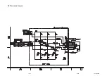
Страница 37: ...Main 2 5 Schematic Diagram 1 8 5 1 8 6 T6700SCM2...

Страница 38: ...tic Diagram 1 8 7 1 8 8 T6700SCM3 Comparison Chart of Models and Marks MODEL MARK MODEL MARK TVCR A2104 A TVCR B2104T F TVCR B2104 B TVCR C2104T G TVCR C2104 C TVCR D2104T H TVCR D2104 D TVCR A2104TG...

Страница 39: ...ic Diagram 1 8 9 1 8 10 T6700SCM4 Comparison Chart of Models and Marks MODEL MARK MODEL MARK TVCR A2104 A TVCR B2104T F TVCR B2104 B TVCR C2104T G TVCR C2104 C TVCR D2104T H TVCR D2104 D TVCR A2104TG...

Страница 40: ...700SCM5 Main 5 5 Schematic Diagram Comparison Chart of Models and Marks MODEL MARK MODEL MARK TVCR A2104 A TVCR B2104T F TVCR B2104 B TVCR C2104T G TVCR C2104 C TVCR D2104T H TVCR D2104 D TVCR A2104TG...

Страница 41: ...o the AC power supply Otherwise it may cause some components in the power supply circuit to fail CAUTION FOR CONTINUED PROTECTION AGAINST FIRE HAZARD REPLACE ONLY WITH THE SAME TYPE FUSE VOLTAGE CHART...

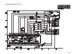
Страница 42: ...1 8 15 1 8 16 H V Power Supply 2 2 Schematic Diagram T6700SCP2...

Страница 43: ...1 8 17 1 8 18 T6700SCCRT CRT Schematic Diagram...

Страница 44: ...SCT Text Schematic Diagram E F G H I Comparison Chart of Models and Marks MODEL MARK MODEL MARK TVCR A2104 A TVCR B2104T F TVCR B2104 B TVCR C2104T G TVCR C2104 C TVCR D2104T H TVCR D2104 D TVCR A2104...

Страница 45: ...1DIV 0 5V 20 s TP003 V OUT Upper WF6 Lower WF1 1DIV 0 2V 2DIV 5V 5ms TP008 C PB WF7 1DIV 0 2V 0 5ms IC301 PIN 52 WF8 1DIV 0 5V 0 5ms TP007 N A PB WF9 1DIV 0 5V 0 5ms IC401 PIN 8 WF10 1DIV 2V 5ms IC30...

Страница 46: ...2 P ON 160V 3 1 2 3 4 CL301B 1 2 3 4 CN301 JUNCTION C CBA BT6600F01012 CN502 H V POWER SUPPLY CBA BT6600F01022 A SENSOR CBA END SENSOR BHF300F01011 A B SENSOR CBA ST SENSOR BHF300F01011 A B 3 V L V C...

Страница 47: ...LD REV 0 2S 0 5S PIN NO CL EJ SS SS AU AU TL LD SW CL SS LD CONT C DRIVE Z ON ON C F R DRUM ROTATION P ON A MUTE H D REC H D PB H PAUSE ON PAUSE PAUSE ON PAUSE OFF PAUSE OFF AU AL AU SF SM EJ AU RS S...

Страница 48: ...P A LD REV FF LD REV LD REV LD FWD LD FWD LD FWD LD FWD LD FWD LD FWD LD FWD REC PAUSE REC REC REW LD REV LD REV LD REV LD REV LD REV LD REV LD REV PAUSE REC or PAUSE STOP EJECT STOP EJECT STOP EJECT...

Страница 49: ...ot Used 18 OUT RF SW Video Head Switching Pulse 19 NU Not Used 20 OUT A MUTE H Audio Mute Control Signal Mute H 21 NU Not Used 22 NU Not Used 23 OUT REC LED Recording LED Control Signal 24 OUT REC LED...

Страница 50: ...ommunication Data 73 NU Not Used 74 IN C SYNC C Sync Input 75 NU Not Used 76 OUT C CONT Capstan Motor Control Signal 77 OUT D CONT Drum Motor Control Signal Pin No Mark IN OUT Signal Name Function 78...

Страница 51: ...Y O 2SC1627Y TPE2 2SC2785 F H J BN1F4M T KTA1267 GR KTA1271 Y KTC3198 GR KTC3199 GR 2SC3619 KTC3503Y MID 32A22F PT204 6B 12 2SA1346 2SC1815 GR TPE2 2SC2120 O TPE2 2SC2120 Y TPE2 2SC3331 T U KRA103M K...

Страница 52: ...PL1 PL1 PL1 PL2 PB5 PL2 PL2 PB4 PB1 PL1 H V Power Supply CBA Text CBA Sensor CBA Main CBA Sensor CBA Junction A CBA Junction C CBA Junction B CBA TB7 TB3 TB21 CRT CBA DG601 CL604 B F See Electrical Pa...

Страница 53: ...2 X2 1 X2 3 X2 3 X2 4 X2 5 X2 6 X2 7 X2 8 D H X2 12 I X2 1 B F X2 9 X2 10 X2 11 X2 2 C G X2 3 X2 4 Comparison Chart of Models and Marks Model Mark TVCR A2104 TVCR B2104 TVCR C2104 TVCR D2104 TVCR A21...

Страница 54: ...SSEMBLED 12 M3X12 0EM406746 L8 FLAT HEAD SCREW T4000UA 0EM404793 L9 SCREW S TIGHT 3X4 BIND HEAD GBMS3040 SP151 SPEAKER S08F02B or DSD0808XQ010 SPEAKER J F097 C5 DSD0808DCP01 TB1 TRAY CHASSIS T6400RA 0...

Страница 55: ...4 CZ 0EMN02428 X2 12 I OWNER S MANUAL TVCR A1404TG GR 0EMN02388 X3 A B C D REMOTE CONTROL 512 ERC001 NE136RD NE136RD X3 E F G H I REMOTE CONTROL 512 ERC001 NE135RD NE135RD X4 DRY BATTERY R6P UM3 or XB...

Страница 56: ...MAVSL100 C160 CHIP CERAMIC CAP CH J 270pF 50V CHD1JJBCH271 C203 CHIP CERAMIC CAP MELF F Z 0 01 F 16V CZM1CZB0F103 C205 CHIP CERAMIC CAP MELF F Z 0 01 F 16V CZM1CZB0F103 C207 ELECTROLYTIC CAP 1 F 50V M...

Страница 57: ...ELECTROLYTIC CAP 1 F 50V M or CE1JMASDL010 Ref No Mark Description Part No ELECTROLYTIC CAP 1 F 50V M or CE1JMASDL1R0 ELECTROLYTIC CAP 1 F 50V M CE1JMASTL1R0 C327 CHIP CERAMIC CAP B K 0 01 F 50V CHD1...

Страница 58: ...F 50V M or CE1JMASDL2R2 ELECTROLYTIC CAP 2 2 F 50V M CE1JMASTL2R2 C694 ELECTROLYTIC CAP 100 F 10V M or CE1AMASDL101 ELECTROLYTIC CAP 100 F 10V M CE1AMASTL101 C703 ELECTROLYTIC CAP 4 7 F 50V M or CE1JM...

Страница 59: ...5 6B or QDTB0MTZJ5R6 ZENER DIODE DZ 5 6BSBT265 NDTB0DZ5R6BS D712 SWITCHING DIODE 1SS133 T 77 or QDTZ001SS133 SWITCHING DIODE 1N4148 NDTZ001N4148 D713 SWITCHING DIODE 1SS133 T 77 or QDTZ001SS133 SWITCH...

Страница 60: ...0KTC3199 TRANSISTOR KTC3198 GR or NQS40KTC3198 TRANSISTOR 2SC1815 GR TPE2 QQS102SC1815 Ref No Mark Description Part No Q708 TRANSISTOR 2SC2785 F or QQSF02SC2785 TRANSISTOR 2SC2785 H or QQSH02SC2785 TR...

Страница 61: ...PER D0 6 P5 0 JW5 0T Ref No Mark Description Part No R266 PCB JUMPER D0 6 P5 0 JW5 0T R267 CHIP RES 1608 1 10W J 10k RRXAJB5Z0103 R268 CHIP RES 1608 1 10W J 3 3k RRXAJB5Z0332 R269 CHIP RES 1608 1 10W...

Страница 62: ...R745 CHIP RES 1608 1 10W J 6 2k RRXAJB5Z0622 R746 CHIP RES 1608 1 10W J 47k RRXAJB5Z0473 R747 CHIP RES 1608 1 10W J 6 2k RRXAJB5Z0622 Ref No Mark Description Part No R748 CHIP RES 1608 1 10W J 2 2k R...

Страница 63: ...6 P12 5 JW12 5T TP009 PCB JUMPER D0 6 P12 5 JW12 5T TP010 PCB JUMPER D0 6 P22 5 JW22 5T TU001 A B D E F H I TUNER UNIT TMQZ2 303A UTUNPLGAL013 TU001 C G TUNER UNIT TMQZ2 413A UTUNPSGAL009 X201 X TAL...

Страница 64: ...P P 0 039 F 50V J CA1J393MS029 C614 FILM CAP P 0 001 F 50V J or CMA1JJS00102 FILM CAP P 0 001 F 50V J CA1J102MS029 C615 FILM CAP P 0 082 F 50V J or CMA1JJS00823 FILM CAP P 0 082 F 50V J CA1J823MS029 C...

Страница 65: ...or QDTZ001SS133 SWITCHING DIODE 1N4148 NDTZ001N4148 D637 SWITCHING DIODE 1SS133 T 77 or QDTZ001SS133 SWITCHING DIODE 1N4148 NDTZ001N4148 D638 SWITCHING DIODE 1SS133 T 77 or QDTZ001SS133 Ref No Mark D...

Страница 66: ...84 R624 CARBON RES 1 4W J 680k RCX4JATZ0684 R626 CARBON RES 1 4W J 1 2k RCX4JATZ0122 Ref No Mark Description Part No R627 PCB JUMPER D0 6 P5 0 JW5 0T R628 CARBON RES 1 4W J 820 RCX4JATZ0821 R629 CARBO...

Страница 67: ...RCX4JATZ0471 R518 CARBON RES 1 4W J 120k RCX4JATZ0124 R519 CARBON RES 1 4W J 15 RCX4JATZ0150 R520 CARBON RES 1 4W J 470 RCX4JATZ0471 R521 CARBON RES 1 4W J 120k RCX4JATZ0124 R522 CARBON RES 1 4W J 15...

Страница 68: ...H I CARBON RES 1 4W J 10k RCX4JATZ0103 R906 E F G H I CARBON RES 1 4W J 1 5k RCX4JATZ0152 R908 E F G H I CARBON RES 1 4W J 1 5k RCX4JATZ0152 R911 E F G H I CARBON RES 1 4W J 1 5k RCX4JATZ0152 R912 E F...

Страница 69: ...enance 2 1 1 Service Fixture and Tools 2 2 1 Mechanical Alignment Procedures 2 3 1 Disassembly Assembly Procedures of Deck Mechanism 2 4 1 Alignment Procedures of Mechanism 2 5 1 Deck Exploded Views 2...

Страница 70: ...Change Deck Periodic Service Schedule Ref No Part Name 1 000 H 2 000 H 3 000 H 4 000 H B2 Cylinder Assembly I I B3 Loading Motor Assembly I B8 Pulley Assembly I I B587 Tension Lever Assembly I I B31...

Страница 71: ...ard material but since it is very thin avoid cleaning it vertically 2 Wait for the cleaned part to dry thoroughly before operating the unit 3 Do not reuse a stained head cleaning stick or a stained ch...

Страница 72: ...Alignment Tape FL6N8 2 Head model FL6NS8 4 Head model Azimuth and X Value Adjustment of ACE Head Adjustment of Envelope Waveform J 2 Guide Roller Adj Screwdriver Available Locally Guide Roller J 3 Mi...

Страница 73: ...that the Moving guide preparations are in the Eject Position 4 Turn the LDG Belt in the appropriate direction shown in Fig M1 until the Moving guide prepara tions come to the Eject Position Stop turni...

Страница 74: ...heck to see that the tape is not creasing and that there is no slack on the supply and take up side Guide Rollers Use a blank tape Adjust the height of the Guide Rollers Supply side and take up side U...

Страница 75: ...e ACE Head Fig M6 1 B X Value Alignment Purpose To obtain maximum PB FM envelope signal at the pre set position of the Tracking Control Circuit align the Horizontal Position of the ACE Head Symptom of...

Страница 76: ...To do this adjust ment turn the top of the Guide Roller with the Guide Roller Adj Screwdriver 3 If the envelope is as shown in Fig M7 adjust the height of Guide Roller 2 Refer to Fig M3 so that the w...

Страница 77: ...f the Audio Control Erase Head is not properly aligned the Audio S N Ratio or Frequency Response will be poor 1 Connect the oscilloscope to the audio output jack on the rear side of the deck 2 Playbac...

Страница 78: ...DM5 7 7 Cylinder Assembly T DM1 DM6 Desolder 3 S 2 8 8 Loading Motor Assembly T DM1 DM7 Desolder LDG Belt 2 S 3 9 9 ACE Head Assembly T DM1 DM7 S 4 10 2 Tape Guide Arm Assembly T DM1 DM8 1 P 2 11 10...

Страница 79: ...ws for lubrication 32 25 Loading Arm SP Assembly B DM2 DM14 Refer to Alignment Sec Page 2 5 1 33 32 Loading Arm TU Assembly B DM2 DM14 Refer to Alignment Sec Page 2 5 1 34 2 25 M Brake TU Assembly T D...

Страница 80: ...2 4 3 Z13PDA 14 13 11 10 12 7 8 30 40 16 39 38 42 41 43 9 34 15 36 35 29 Fig DM1 Top View 46 32 20 33 24 25 27 26 23 28 31 21 22 Bottom View Fig DM2...

Страница 81: ...D Pull up Slide 1 2 A S 10 3 6 6 L 2 Pin A Hole A Pin B Hole B L 1 First insert 6 diagonally in 3 as shown below Then install 6 in 3 while pushing L 1 in a direction of arrow After installing 6 in 3...

Страница 82: ...7 A 8 9 S 4 S 3 LDG Belt 8 Pin of 12 Pin of 10 Groove of 28 View for A Fig DM8 1 When reassembling 10 and 12 confirm that pin of 10 and pin of 12 are in the groove of 28 as shown 28 11 13 12 A 10 L 4...

Страница 83: ...to Fig A Fig A 13 12 P 3 Fig B Top view Install pin of 12 in groove of 28 Refer to Fig B 28 Hold 12 and 13 till groove of pin of chassis looks and fit 13 in notch of chassis Then turn a few 13 while...

Страница 84: ...5 28 When installing 23 install the spring P 5 to 28 as shown in the left figure and then install 23 while pressing the spring P 5 to the direction of the arrow in the left figure and confirming that...

Страница 85: ...and 28 as shown Bottom View 28 25 28 Top View First tooth on 44 First groove on 28 Installation of 25 When reassembling 28 align the first groove on 28 to the first tooth on 44 as shown Fig DM13 2 Fig...

Страница 86: ...2 4 9 Z13PDA Fig DM16 43 41 42 L 13 Fig DM17 44 45 Slide P 9...

Страница 87: ...the mechanical or electrical parts Alignment points in Eject Position Alignment 1 Loading Arm SP and TU Assembly Install Loading Arm SP and TU Assembly so that their triangle marks point to each other...

Страница 88: ...MH D Blue grease SLIDUS OIL 150 B12 B492 B11 B571 B37 Some Ref Numbers are not in sequence B126 B8 B121 B426 B560 L1450 L1450 L1466 B501 Chassis Assembly Top View Lubricating Point Chassis Assembly Bo...

Страница 89: ...G84M Yellow grease B508 B414 View for A Grease point B516 B559 B52 B134 B133 B568 B569 B565 B417 Some Ref Numbers are not in sequence Bottom Side Grease point B507 B488 B570 B491 B513 B502 Bottom Side...

Страница 90: ...View 3 Mark Description Floil G 684G or Multemp MH D Blue grease SLIDUS OIL 150 B563 B300 B562 B482 B355 B354 B483 B425 L1321 B347 L1321 B313 L1341 B303 B555 B514 Some Ref Numbers are not in sequence...

Страница 91: ...11 0VM412972 B300 C DRIVE LEVER TU MK12 0VM203773 B303 F DOOR OPENER MK12 0VM203751C B313 C DRIVE SPRING MK12 0VM414145 B347 GUIDE HOLDER A MK10 0VM304920 B354 SLIDER TU MK12 0VM101172F B355 SLIDER SP...

Страница 92: ...0VM412550 L1051 SCREW B TIGHT M2 6X6 PAN HEAD GPMB9060 L1053 SCREW S TIGHT M2 6X8 WASHER HEAD GCMS9080 L1151 SCREW SEMS M3X4 PAN HEAD or CPM33040 SCREW SEMS M2 6X4 PAN HEAD CPM39040 L1191 SCREW S TIGH...

Страница 93: ...TVCR A2104 B2104 C2104 D2104 A2104T B2104T C2104T D2104T A2104TG T6700EA T6701BB T6702FC T6703RD T6720EA T6721BB T6722FC T6723RD T6724EE 2004 03 09...

Отзывы: