1-5-1
E7B20DC
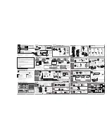
CABINET DISASSEMBLY INSTRUCTIONS
1. Disassembly Flowchart
This flowchart indicates the disassembly steps to gain
access to item(s) to be serviced. When reassembling,
follow the steps in reverse order. Bend, route, and
dress the cables as they were originally.
2. Disassembly Method
Note:
(1) Identification (location) No. of parts in the figures
(2) Name of the part
(3) Figure Number for reference
(4) Identification of parts to be removed, unhooked,
unlocked, released, unplugged, unclamped, or
desoldered.
P = Spring, L = Locking Tab, S = Screw,
CN = Connector
* = Unhook, Unlock, Release, Unplug, or Desolder
e.g. 2(S-2) = two Screws (S-2),
2(L-2) = two Locking Tabs (L-2)
(5) Refer to “Reference Notes.”
Reference Notes
1. CAUTION 1: Locking Tabs (L-1) and (L-2) are
fragile. Be careful not to break them.
ID/
Loc.
No.
Part
Removal
Fig.
No.
Remove/*Unhook/
Unlock/Release/
Unplug/Desolder
Note
[1]
TOP COVER
D1 8(S-1)
---
[2]
FRONT
ASSEMBLY
D2 *6(L-1), *3(L-2)
1
[3]
DVD
MECHANISM
& DVD MAIN
CBA
ASSEMBLY
D3
4(S-2), *CN101,
*CN701, LOCKING
CARD SPACERS
---
[4]
SW CBA
D4 (S-3), Desolder
---
[5]
PCB HOLDER D4 2(S-4)
---
[6]
POWER
SUPPLY CBA
D4 2(S-5), *CN1152
---
[7]
POWER
HOLDER
D4 (S-6)
---
[8]
FAN COVER
D5 2(S-7)
---
[9]
FAN
D5
FAN EARTH,
*CN1601
---
[10] REAR PANEL
D5
(S-8), 6(S-9),
2(S-10)
---
[11] AV CBA
D6 3(S-11)
---
[12] JACK CBA
D6 Desolder
---
[1] TOP COVER
[2] FRONT ASSEMBLY
[9] FAN
[8] FAN COVER
[3] DVD MECHANISM & DVD MAIN CBA ASSEMBLY
[4] SW CBA
[5] PCB HOLDER
[6] POWER SUPPLY CBA
[7] POWER HOLDER
[10] REAR PANEL
[11] AV CBA
[12] JACK CBA
[13] AFV CBA
[13] AFV CBA
D6 Desolder
---
↓
(1)
↓
(2)
↓
(3)
↓
(4)
↓
(5)
ID/
Loc.
No.
Part
Removal
Fig.
No.
Remove/*Unhook/
Unlock/Release/
Unplug/Desolder
Note
[1] TOP COVER
(S-1)
(S-1)
(S-1)
Fig. D1
Содержание DR-B3737
Страница 1: ...SERVICE MANUAL DVD RECORDER DR C3835 DR B3737...
Страница 33: ...1 10 11 E7B22SCAV4 AV 4 5 Schematic Diagram...
Страница 34: ...1 10 12 E7B22SCAV5 AV 5 5 Schematic Diagram...
Страница 36: ...1 10 14 AFV Schematic Diagram E7B22SCAFV Comparison Chart of Models and Marks MODEL MARK DR C3835 A DR B3737 B...
Страница 37: ...1 10 15 SW Schematic Diagram Jack Schematic Diagram E7B22SCJ E7B22SCSW...
Страница 38: ...1 10 16 BE7B00F01011A AV CBA Top View...
Страница 43: ...1 10 21 AFV CBA Top View BE6800F01091 AFV CBA Bottom View...
Страница 62: ...DR C3835 DR B3737 E7B22FD E7B25BD 2006 04 28...