


1-6-1
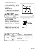
H9903DC
CABINET DISASSEMBLY INSTRUCTIONS
1. Disassembly Flowchart
This flowchart indicates the disassembly steps to gain
access to item(s) to be serviced. When reassembling,
follow the steps in reverse order. Bend, route, and
dress the cables as they were originally.
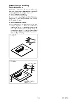
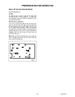
2. Disassembly Method
Note:
(1): Identification (location) No. of parts in the figures
(2): Name of the part
(3): Figure Number for reference
(4): Identification of parts to be removed, unhooked,
unlocked, released, unplugged, unclamped, or
desoldered.
P=Spring, L=Locking Tab, S=Screw,
CN=Connector
*=Unhook, Unlock, Release, Unplug, or Desolder
e.g. 2(S-2) = two Screws (S-2),
2(L-2) = two Locking Tabs (L-2)
(5): Refer to “Reference Notes.”
ID/
LOC.
No.
PART
REMOVAL
Fig.
No.
REMOVE/*UNHOOK/
UNLOCK/RELEASE/
UNPLUG/DESOLDER
Note
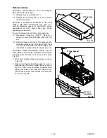
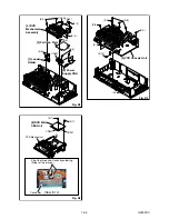
[1]
Top Case
D1 8(S-1)
-
[2]
Front
Assembly
D2 *3(L-1), *3(L-2)
1
1-1
1-2
[3]
Top Bracket
D2 3(S-2)
-
[4]
DVD
Mechanism
Assembly
D3
4(S-3), *CN401,
*CN601
-
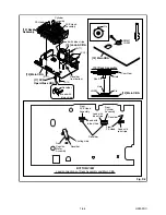
[5]
Partition
Plate
D3 (S-4)
-
[6]
Power
Supply CBA
D3 2(S-5), CN501
-
[7]
Loader
Holder
D3 2(S-6)
-
[8]
DVD Main
CBA Unit
D4
2(S-7), *CN201,
*CN301
2
2-1
2-2
3
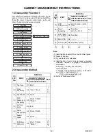
[1] Top Case
[2] Front Assembly
[3] Top Bracket
[4] DVD Mechanism Assembly
[8] DVD Main CBA Unit
[5] Partition Plate
[7] Loader Holder
[6] Power Supply CBA
[9] VCR Chassis Unit
[10] Deck Assembly
[11] DVD Open/Close CBA
[12] Main CBA
[13] Jack-A CBA
[9]
VCR
Chassis Unit
D5
5(S-8), 2(S-9), (S-10),
(L-3)
-
[10]
Deck
Assembly
D6
Desolder,
2(S-11), (S-12)
4,5
[11]
DVD Open/
Close CBA
D6 Desolder
-
[12] Main CBA
D6 ----------
-
[13] Jack-A CBA D6 Desolder, 2(S-13)
-
↓
(1)
↓
(2)
↓
(3)
↓
(4)
↓
(5)
ID/
LOC.
No.
PART
REMOVAL
Fig.
No.
REMOVE/*UNHOOK/
UNLOCK/RELEASE/
UNPLUG/DESOLDER
Note
Содержание DDVR-6830
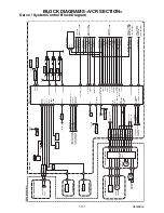
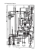
Страница 36: ...1 12 6 H9903SCM4 Main 4 8 Schematic Diagram VCR Section...
Страница 37: ...1 12 7 H9903SCM5 Main 5 8 Schematic Diagram VCR Section...
Страница 38: ...1 12 8 H9903SCM6 Main 6 8 Schematic Diagram VCR Section...
Страница 40: ...1 12 10 H9903CM8 Main 8 8 Schematic Diagram VCR Section...
Страница 42: ...1 12 12 H9903SCJ Jack A Schematic Diagram VCR Section...
Страница 43: ...1 12 13 H9903SCAFV AFV Schematic Diagram VCR Section...
Страница 45: ...1 12 15 H9903SCD2 DVD Main 2 3 Schematic Diagram DVD Section...
Страница 47: ...1 12 17 H9903SCD3 DVD Main 3 3 Schematic Diagram DVD Section...
Страница 75: ...DDVR 6830 DPVR 6830 H9903 04ED 2005 07 23...


