background image

 
TeamPoS 3000 XL and XL

2


Installation 


D900000145 

Issue 3 

5-77 


5.18.2  Installing the Central Filler 

 
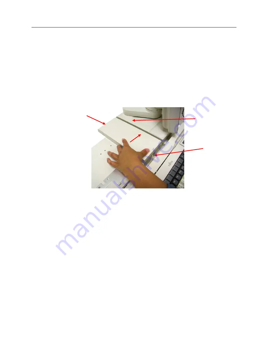
The Central Filler is used to occupy the free space on a standard control unit with a stacked LCD 
(either D22 or D25) and a model DT50III printer.  The cable for the keyboard is threaded 
through the underside of the central filler and therefore the keyboard is installed at the same time 
as the Central Filler. 
 

1.


Install Central Filler by placing it on the chassis with the front edge aligned with the 
central lip and ½” to the left of the LCD (facing the front of the unit). 


2.


Slide Central Filler to the right so that the front and back of the Central Filler align with 
the front and back of the LCD. 

Central Filler 

LCD Stand Installed on 

Standard TeamPoS 3000 

Notice keyboard not 

seated, cable under the 

Central Filler 

Slide Right 

Содержание TeamPoS 3000 XL

Страница 1: ...Installation Maintenance Manual TeamPoS 3000 XL and XL2 ...

Страница 2: ...TeamPoS 3000 Installation and Maintenance Manual ...

Страница 3: ... liability for any error or omission The development of Fujitsu products and services is continuous and published information may not be up to date It is important to check the current position with Fujitsu Transaction Solutions Inc This document is not part of a contract or license save insofar as may be expressly agreed Issue Date Revision September 5 2006 1 August 1 2008 2 August 7 2009 3 ...

Страница 4: ...ass A digital apparatus meets all the requirements of the Canadian Interference Causing Equipment Regulations Cet appareil numérique de la classe A respecte toutes les exigences du Règlement sur le matériel brouilleur du Canada Radio Frequency Interference Requirements Europe This apparatus has been tested and found to comply with the limits for a Class A digital device per EN55022 for use in Info...

Страница 5: ...ARNING The LCD s used with this product may contain a backlight that contains mercury Please dispose of according to local state or federal laws Hg LAMP S INSIDE THIS PRODUCT CONTAIN MERCURY AND MUST BE RECYCLED OR DISPOSED OF ACCORDING TO LOCAL STATE OR FEDERAL LAWS ...

Страница 6: ...4 3 3 2 Model 133AU Keyboard 3 4 3 3 3 Model 92U Keyboard 3 5 3 4 Cash Drawers 3 5 3 4 1 Model TP15 Cash Drawer Standard 3 5 3 4 2 Model TP5C Cash Drawer Compact 3 7 3 5 Displays 3 5 1 Model 22 LCD and Model D25 LCD Displays 3 8 3 5 2 LCD VESA Bracket Mounting 3 9 3 5 3 Model D22 D25 LCDs on Stacked Stand 3 10 3 5 4 Model D22 D25 LCDs w MSR 3 10 3 5 5 Model D22 D25 LCD on Stacked Stand w MSR VF60 ...

Страница 7: ... 20 5 10 Installing PCI Add In Cards 5 22 5 11 Installing the I O Boards 5 24 5 11 1 No I O Board 5 25 5 11 2 Powered USB I O Board 5 26 5 11 3 Combo Board 5 29 5 11 4 Combo Board with Com Board XL Motherboard only 5 33 5 12 Port Labels 5 38 5 13 Standard Bracket Locations 5 39 5 14 Installing the LCD Stands 5 40 5 14 1 Single Stacked LCD Stand 5 41 5 14 2 Single Dispersed LCD Stand 5 46 5 14 3 Du...

Страница 8: ...placing XL2 7 6 Replacing the CD DVD Drive 7 22 Motherboard Memory 7 19 7 7 Replacing Battery Backup 7 25 7 8 Removing the backplane assembly 7 27 7 9 Replacing I O Boards 7 29 7 9 1 No I O Board 7 30 7 9 2 Powered USB I O Board 7 30 7 9 2 1 USB Board Jumper Settings 7 34 7 9 3 Combo Board 7 35 7 9 3 1 Combo Board Installation 7 37 7 9 3 2 Combo Board Diagram 7 39 7 9 3 3 Combo Board Jumper Settin...

Страница 9: ...S Setup Motherboard 9 3 9 1 4 BIOS Features Setup Motherboard 9 4 9 1 5 CPU Feature Setup Motherboard 9 5 9 1 6 Hard Disk Boot Priority Motherboard 9 6 9 1 7 Advance Chipset Features Setup Motherboard 9 7 9 1 8 Integrated Peripherals Setup Motherboard 9 8 9 1 9 USB Configuration setup Motherboard 9 9 9 1 10 On Chip IDE Device Setup Motherboard 9 9 9 1 11 Onboard Device Setup Motherboard 9 10 9 1 1...

Страница 10: ...Feature Setup XL Motherboard 10 10 2 10 1 13 ICH SATA PATA Control Sup Menu Setup XL Motherboard 10 11 2 10 1 14 Super IO Feature Setup XL 10 12 2 10 1 15 Hardware Monitor Feature Setup XL Motherboard 10 13 2 10 1 16 Other Feature Setup XL Motherboard 10 14 2 10 1 17 Security Setup XL Motherboard 10 15 2 10 1 18 TPM State Setup XL Motherboard 10 16 2 10 1 19 Power setup XL Motherboard 10 16 2 10 1...

Страница 11: ...and peripherals It supports standard PC components such as high performance CPU s memory hard disk video and audio It can be used as a PC to run standard PC applications such as word processing spreadsheets etc subject to operating system and licensing restrictions This controller offers duplicate 2 5 hard disk drives on board LAN 12 1 or 15 LCD s USB Combo and COM I O boards and on a variety of s...

Страница 12: ...TeamPoS 3000 XL and XL2 Overview D900000145 Issue 3 1 2 1 1 TeamPoS 3000 Control Unit Flow Diagram XL Motherboard only ...

Страница 13: ...CD CDRW DVD Docking Backplane Power Supply Unit OR TeamCombo Board Optional Com Board Optional Powered USB 24V DVI D Analog RGB VGA LAN PS 2 KB PS 2 Mouse COM 1 COM 2 Drawer Line out Mic In Partial Battery Backup Full Backup Battery PCI slot Powered USB Optional 12V PWR USB 100 240 VAC 12V PWR USB 12V PWR USB 12V PWR USB 12V PWR USB 12V PWR USB 12V PWR USB 12V PWR USB 12V PWR USB RS232 COM Port 3 ...

Страница 14: ...ches SD USB 1 Power Switch On Off button located behind drop down window Shown here Drop down window in up position USB 2 Power LED Green Battery Backup LED Blinking Yellow Port Power LED Reset Switch Button Dump Switch Button Do not use LAN LED Green Port On Off Switch 5 VDC MB Power LED Amber Visible only when the front panel is removed Hard Disk Drive LED Green ...

Страница 15: ...oor Resets terminal all data in memory will be lost Dump Switch Inside front panel door Not used Port Switch Inside front panel door Default setting is ON right position Turns on off power to all RS232 ports including COM 1 COM 2 N A 5VDC MB Power LED Behind front panel Amber Indicates AC power is supplied to the power supply and standby voltages for motherboard are available Note Do not remove mo...

Страница 16: ... Digit Spare 0 12th Digit Spare 0 No flash memory 1 1 GB Flash 11th Digit Power Cord 0 No Power Cord 1 US White 2 US Black 6th Digit Hard Drive 0 No Hard Drive 1 40 GB Hard Drive 2 80 GB Hard Drive 7th Digit 2nd Hard Drive 0 No 2nd Hard Drive A RAID 0 B RAID 1 C Drive C D 10th Digit CD DVD 0 No CD 1 CDR White 2 CDR Black 3 CD RW DVD White 4 CD RW DVD Black 4th Digit Memory 1 256 MB DDR Memory 2 51...

Страница 17: ...TeamPoS 3000 XL and XL2 Overview D900000145 Issue 3 1 7 This Page Intentionally Left Blank ...

Страница 18: ...onmental Specifications The figure below shows a typical integrated configuration for the TeamPoS 3000 XL2 black without cash drawer Depending on the store environment the configuration and components may differ The tables in the remainder of this section list the environmental specifications ...

Страница 19: ...enance area mm inches Front 1000 1000 Rear 1000 1000 Right 1000 1000 Left 1000 1000 Power requirements Voltage AC100 240 AC100 240 Supplied from the main unit Supplied from the main unit Frequency 50 60Hz 50 60Hz Dissipation power W Max 270 270 120W 144W Temperature F Operating 0 40 32 104 0 40 32 104 5 45 41 113 0 40 32 104 Not operating 5 50 23 122 5 50 23 122 10 50 14 122 5 50 23 122 Humidity N...

Страница 20: ...ght 285 9 15 16 295 11 100 4 Weight kg lbs 2 3 5 2 3 6 8 0 8 1 8 Power requirements Voltage Supplied from the main unit Supplied from the main unit Supplied from the main unit Dissipation power W Max 10W 12W 4W Specifications Unit Cash drawer Standard type Cash drawer Compact type External dimensions in mm inches Width 450 17 343 13 Depth 450 17 450 17 Height 122 4 121 4 Weight kg lbs 9 7 21 4 6 3...

Страница 21: ...TeamPoS 3000 XL and XL2 Environmental Specifications D900000145 Issue 3 2 4 This page intentionally left blank ...

Страница 22: ...nd customer display are stacked on top of the control unit This requires brackets to be installed on the control unit that restrain movement of the peripherals The cash drawer if stacked is located under the control unit In this case brackets are installed on top of the cash drawer to restrain the controller 2 12 LCD Stacked Configuration Dimensions Note Dimensions taken with monitor facing straig...

Страница 23: ... stand rotated to its maximum width and with the monitors at maximum rotation and tilt the maximum width for this configuration is 27 1 8 and maximum depth is 27 The printer overhangs the rear edge by 3 4 inch 3 1 2 Model D25 D25IR LCD in Dual Stacked Configuration 450 17 450 17 3 4 height 490 19 footprint 503 19 to end of printer 450 17 3 4 450 17 height 490 19 503 19 3 4 to end of printer 602 23...

Страница 24: ... The largest space required to accommodate the widest spread of the monitor arms and the greatest tilt of the LCD is 681 27 wide x 762 30 deep x 450 17 3 4 high 3 2 Control Units Compact TeamPoS 3000 XL and XL Control Unit without brackets installed 2 Standard TeamPoS 3000 XL and XL Control Unit without brackets installed 2 450 17 490 19 110 4 1 2 incl feet 348 13 6 8 450 17 7 8 112 4 1 2 incl fee...

Страница 25: ... 3 4 3 3 Keyboards 3 3 1 Model 133 UQ Keyboard Dimensions PIN s 90000829 white 900001519 black 3 3 2 Model 133 AU Keyboard Dimensions PIN s 11001689 white 11001699 black 450 17 202 7 7 8 43 1 6 8 Height at the rear 450 17 202 7 7 8 43 1 6 8 height at rear ...

Страница 26: ...yboard Dimension PIN 90000630 3 4 Cash Drawers 3 4 1 Model TP15 Cash Drawer Standard 11001467 white w o lock 11000153 white w lock 11001468 black w o lock 11000154 black w lock Standard Cash Drawer 140 5 140 5 3 8 397 15 7 8 50 2 450 17 450 17 122 4 incl for feet 760 30 450 17 ...

Страница 27: ...TeamPoS 3000 XL and XL2 Dimensions D900000145 Issue 3 3 6 Standard Cash Drawer in Open Position 122 4 incl 3 4 for feet ...

Страница 28: ...e 3 3 7 3 4 2 Model TP5C Cash Drawer Compact 11000147 white w o lock 11000149 white w lock 11000148 black w o lock 11000150 black w lock Closed Cash Drawer Cash Drawer open 746 29 3 8 343 13 3 4 121 4 incl 3 4 for feet 343 13 450 17 121 4 incl for feet ...

Страница 29: ...tal use a DVI cable Download video drivers from the following website http us fujitsu com support The D22 is available with 5 wire resistive touch screen The D25 is available with 5 wire resistive or infrared touch Options include a 3 track MSR which can be added separately or with a 5x8 keypad MSR future release Speakers are standard The D25 with MSR and keypad can only be stacked on a standard P...

Страница 30: ...2 LCD VESA Bracket Mounting Although usually mounted on Fujitsu stands the D22 and D25 LCD s can both use a standard 100mm 4 VESA mount The cosmetic back panel has predrilled holes for the screws to pass through and attach to the back of the monitor D25 LCD Back Panel for D25 360 14 295 11 60 2 3 8 130 5 1 8 83 3 80 3 1 8 35 1 3 8 ...

Страница 31: ... 5 3 Model D22 D25 LCD s on Stacked Stand PIN s 11000064 white 11000073 black D22 D25 3 5 4 Model D22 D25 LCD s w MSR PIN s 11002245 white 11002248 black D22 D25 300 11 5 8 280 11 360 14 340 13 3 8 280 11 300 11 7 8 300 12 280 11 355 14 280 11 340 13 415 16 3 8 ...

Страница 32: ...ns D900000145 Issue 3 3 11 3 5 5 Model D22 D25 LCD on Single Stacked Stand w MSR VF60 Display VF60 PIN s 11000076 white 11000077 black Telescoping Pole PIN s 11000078 white 11000079 black 280 11 450 17 355 14 280 11 415 16 3 8 450 17 ...

Страница 33: ...TeamPoS 3000 XL and XL2 Dimensions D900000145 Issue 3 3 12 3 5 6 Model D22 D25 LCD on Dual Stacked Stand PIN s 11000481 white 11000484 black 370 14 360 14 3 16 460 18 ...

Страница 34: ...ssue 3 3 13 3 5 7 Model D25 D25 on Dual Stacked Stand PIN s 11000742 744 white 11000745 747 black 3 5 8 Model D22 D22 on Dual Stacked Stand PIN s 11000738 110001493 white 11000741 11001492 black 460 18 370 14 360 14 3 16 300 11 7 8 460 18 325 12 6 8 ...

Страница 35: ... The customer display is mounted on a stacked adjustable pole which reaches up to 16 3 from the pole base to the top of the display The display rotates 330 horizontally and tilts 30 vertically VF60 PIN s 11000076 white 11000077 black Telescoping Pole PIN s 11000078 white 11000079 black 245 9 5 8 100 4 300 413 11 13 16 16 2 8 Adjustable 210 8 210 8 300 13 247 11 5 8 300 11 7 8 360 14 ...

Страница 36: ...VF60 Customer Display dispersed VF60 PIN s 11000076 white 11000077 black Dispersed Customer Display Pole Kits White 11000300 11000302 11000304 Black 11000301 11000303 11000305 245 9 5 8 245 9 5 8 245 9 5 8 100 4 100 4 100 4 90 3 90 3 90 3 708 27 7 8 408 16 268 10 5 8 ...

Страница 37: ... for the TeamPoS 3000 XL and XL2 the DT50III and the CT10 Their dimensions are show in the figures that follow 3 6 1 Model DT50III Printer PIN s 11000187 white 11000197 black 3 6 2 Model CT10 Printer PIN s 110000133 white 110000134 black 127 5 207 8 1 8 134 5 Lip extends 19 or 298 11 184 7 190 7 3 8 ...

Страница 38: ...TeamPoS 3000 XL and XL2 Dimensions D900000145 Issue 3 3 17 This page intentionally left blank ...

Страница 39: ...g list have been included in the shipment If components are missing contact your Help Desk for instructions Then report shortages and damage to Customer Care The customer needs to provide the sales order number and a description of the piece of equipment damaged The customer should then telephone 1 800 780 5525 and a Customer Care representative will arrange for replacement Customer Care is not re...

Страница 40: ...ck should surround all protruding edges switches and surfaces Parts shipped in a package separate from the unit must also be repacked and included in the return Each return must include the following information Description of the equipment defect RMA number received from Customer Care representative Order number Date received Name address and phone number of the person making the return 4 4 Using...

Страница 41: ...s are met an electrical contractor familiar with computer equipment should be hired This section provides the electrical supply data and main power cable information to prepare a site for the installation of the TeamPoS 3000XL and XL2 Series terminal This product is also designed for IT power systems with phase to phase voltage of up to 240V Before installing the terminal check the power lines for...

Страница 42: ...y requirements a Line noise limitations must not exceed 1250V with a maximum 1µs duration and the repetition rate not to exceed 100Hz b Socket outlets must provide protective earth grounding and be of a polarized type c Before installing the terminal check the power lines for loads that could cause large variations in voltage Electrical devices that use a great deal of power such as air conditione...

Страница 43: ...ed across a sharp edge DO NOT continue to operate the equipment if you have ANY doubt about it working normally or if it is damaged in any way Instead switch it off and if the equipment is pluggable remove the supply cord and contact your local service agent DO NOT remove any fixed covers unless you are qualified authorized to do so for the preparation of the equipment There are no user serviceabl...

Страница 44: ...lowing amperage requirements Property Value or Description Grounding The terminals are Class 1 equipment and must be supplied via a socket outlet which has a protective ground contact connected to the protective ground of the terminal Power system The terminals are designed for use on a power system with a grounded neutral i e a TN or TT power system The terminals must not be directly connected to...

Страница 45: ...on The power supply cord is used as the main disconnect device Ensure that the socket outlet is located installed near the equipment and is easily accessible 4 10 Warning Labels The equipment contains warning labels shown below Do not remove any warning label If a label becomes damaged or soiled to the point where it is illegible contact your Customer Service Engineer Interior of the front panel o...

Страница 46: ...TeamPoS 3000 XL and XL2 Site Preparation D900000145 Issue 3 4 8 Back View of control unit Bottom of the TeamPoS Controller ...

Страница 47: ...rom the factory or at configuration centers Others will be configured during installation This section shows how to access the control unit components to add or change configurations and installation of Team PoS 3000 peripherals Accessing the TeamPoS 3000 internal components always requires the removal of the front panel 5 1 1 Front Panel Removing the front panel gives access to the motherboard di...

Страница 48: ...0145 Issue 3 5 2 2 Loosen thumbscrew 3 The metal locking tab behind the thumbscrew will likely drop down and unlock of its own accord If not gently pull down on the locking tab 4 Rock front panel out at the top and remove Thumbscrew Locking Tab ...

Страница 49: ...e way around 8 Lift up on the metal tab located behind the thumbscrew and hold up while tightening the screw 9 Close the front door 10 Use the keys to then lock the front door 5 1 2 Rear Panel Removing the rear panel gives you access to the docking backplane 1 To remove the rear panel lift up on the locking tabs at the sides of the rear panel 1 2 Pull back to remove This gives you access to the do...

Страница 50: ... 5 2 Removing the motherboard assembly Caution Be sure to observe all ESD precautions and power off procedures 1 Remove the back panel See Section 5 1 2 2 Disconnect the AC power cord from the controller 3 Remove the front panel See Section 5 1 1 The Yellow LED should be off See Section 1 2 4 Remove hard disk drive shield by pushing in on the right side and pulling outward ...

Страница 51: ...reinstall make sure that the assembly rails line up with the rails in the chassis 8 Slide the motherboard assembly in with the release lever at 45 angle 9 Push in slowly until motherboard assembly engages the lever 10 Use the lever to fully seat the motherboard assembly 11 Reinstall the front panel and reconnect the power cable See Section 5 1 1 12 Reinstall the back panel See Section 5 1 2 ...

Страница 52: ... Remove the rear panel from the controller see Section 5 1 2 2 Disconnect the AC power cord from the controller 3 Remove the front panel See Section 5 1 1 and then yellow LED should be off See Section 1 2 4 Remove the motherboard assembly see Section 5 2 5 Remove the heat sink by loosening the 4 spring loaded screws that attach it to the motherboard There is a mounting bracket on the bottom of the...

Страница 53: ...ockwise to the lock position 9 Place the heat sink over the CPU with fins aligned front to back and secure the heat sink with the four screws attached to it Grip the heat sink bracket to hold it in place while the spring mounted screws are tightened CPU Lock Unlock 1 4 turn counter clockwise Lock 1 4 turn clockwise Align arrows here White arrow on socket Note When replacing the CPU do not reuse th...

Страница 54: ... 11 Reinstall the front panel and reconnect the power cable See Section 5 1 1 12 Reinstall the back panel see Section 5 1 2 5 4 Installing the Hard Disk Drives Caution Be sure to observe all ESD precautions and power off procedures 1 Remove the front panel See Section 5 1 1 2 Remove hard disk drive shield ...

Страница 55: ...k drive to hard drive bracket and secure with four M3 x 6 screws but do not over tighten the screws 4 Slide the new hard disk drive into the bay making sure that the runners align with the guides 5 Press firmly to make the connection and reinstall hard disk drive shield 6 Reinstall the front panel See Section 5 1 1 ...

Страница 56: ...memory sockets or slots and can use 256MB 512MB or 1GB DDR memory in combination 1 Remove the rear panel See Section 5 2 2 Disconnect the AC power cord from the controller 3 Remove the front panel See Section 5 1 1 The yellow LED should be off See Section 1 2 4 Remove the motherboard assembly See Section 5 2 5 Insert memory or additional memory into an empty socket There is only one way the memory...

Страница 57: ... locked into place 7 Reinstall the motherboard See Section 5 2 8 Reinstall the front panel and reconnect the power cable See Section 5 1 1 9 Reinstall the back panel See Section 5 1 2 10 If this is a memory upgrade install the upgrade label that comes with the upgrade kit on the side of the unit near the serial number ...

Страница 58: ...ct the AC power cord from the controller 3 Remove the front panel See Section 5 1 1 Yellow LED should be off See Section 1 2 4 Remove the motherboard assembly See Section 5 2 5 Insert memory or additional memory into the bottom socket There is only one way the memory stick will fit With the motherboard seated in front as shown in the picture below angle the stick approximately 30 pressing to the l...

Страница 59: ...s for the first XL2 Motherboard w o memory sticks XL2 Motherboard w 1 memory ready to install XL2 Motherboard with 1 stick installed XL2 Motherboard w 2nd stick ready to install 8 Reinstall the motherboard See Section 5 2 9 Reinstall the front panel and reconnect the power cable See Section 5 1 1 10 Reinstall the back panel See Section 5 1 2 Memory Sockets Memory Memory ...

Страница 60: ...TeamPoS 3000 XL and XL2 Installation 5 14 Issue 3 D900000145 11 If this is an upgrade install the upgrade label that comes with the upgrade kit on the side of the unit near the serial number ...

Страница 61: ... of the motherboard assembly and requires a narrow Phillips head screwdriver to install 1 Remove the rear panel See Section 5 1 2 2 Disconnect the AC power cord from the controller 3 Remove the front panel See Section 5 1 1 The yellow LED should be off 4 Remove motherboard assembly See Section 5 2 5 Remove the metal blanking plate by removing the 2 screws holding it in place Retain the screws ...

Страница 62: ...ve forward so that it fits into the opening in the chassis and the holes in the bracket are aligned with the holes in the chassis Attach the bracket to the chassis with the two screws retained in Step 5 above 7 The power cable and ribbon cable come attached to the back of the CD DVD drive Attach the other end of the white power cable to the motherboard as shown in the photo Hook Tabs White Power C...

Страница 63: ... the attached photo 9 Reinstall the motherboard See Section 5 2 Make sure the cables are clear of any obstruction 10 Pop out the cosmetic filler in the front panel 11 Reinstall the front panel and reconnect the power cable See Section 5 1 1 12 Reinstall the back panel See Section 5 1 2 Ribbon cable is Z folded to fit White power cable loops around ribbon cable Cosmetic Filler ...

Страница 64: ...nd power off procedures The partial backup battery is located on the front of the TeamPoS 3000XL and XL2 on the left 1 Remove the rear panel See Section 5 1 2 2 Disconnect the AC power cord from the controller 3 Remove the front panel See Section 5 1 and the yellow LED should be off See Section 1 2 4 Remove the protective front metal covering as shown ...

Страница 65: ...e battery 6 Connect the white connector attached to the battery to the white power cable in the controller Tuck the cables out of the way on top of the battery 7 Reinstall the front panel and the power cable See Section 5 1 1 8 Reinstall the front panel and reconnect power cable See Section 5 1 1 9 Reinstall the rear panel See Section 5 1 2 ...

Страница 66: ... Remove the rear panel See Section 5 1 2 2 Disconnect the AC power cord from the controller 3 Remove the front panel See Section 5 1 1 The yellow LED should be off See Section 1 2 4 Unseat the motherboard assembly See Section 5 2 5 At the rear remove the locking screw on the right hand side of the backplane assembly Looking from the rear the power supply is on the right ...

Страница 67: ...ply will slide out Pull out with both hands 7 Reinstall backplane assembly and secure into place with slide bar and locking screw before reseating the motherboard 8 Reinstall the motherboard See Section 5 2 9 Reinstall the front panel and reconnect the power cable See Section 5 1 1 10 Reinstall the back panel See Section 5 1 2 Locking Screw Lift up and out ...

Страница 68: ...ront panel See section 5 1 1 The yellow LED should be off See Section 1 2 4 Unseat the motherboard by pulling gently on the seating lever See section 5 2 5 Remove the backplane assembly See Section 5 9 6 Viewing the backplane assembly from the rear there is a vertical slot on the left hand side for the height PCI card The PCI connector is located directly below this slot 7 Remove the locking screw...

Страница 69: ...e screw that was used for the blanking plate 10 Reinstall the backplane assembly and secure into place using the locking bar before reseating the motherboard 11 Reinstall the motherboard See Section 5 2 12 Reinstall the front plate and reconnect the power cable See Section 5 1 1 13 Reinstall the back plate See Section 5 1 2 PCI Connector ...

Страница 70: ... powered USB ports 3 Combo Board The XL Combo Board has 6 powered USB ports and 2 RS232 ports On the XL2 there are only 5 active USB ports and 2 RS232 ports 4 Combo Board with COM Board Combo board in 3 plus COM Board with 3x RS232 ports COM board cannot be used with the XL2 motherboard Note The Combo board cannot be combined with single powered USB The Combo board can be installed without the COM...

Страница 71: ...re connected to the backplane assembly Refer to the instructions that follow to identify which connectors support which I O board 5 11 1 No I O Board Backplane assembly will have two filler plates a long one and a short one PCI Connector J12 J10 J11 J13 Power Supply Connectors ...

Страница 72: ...power source LPS requirements These ports are limited to only allowing 24V Retail POS RS232 or powered USB peripherals that do not exceed a rated current of 4 Amps and are provided with a Fire Enclosure Rated Min V 1 or Metal Peripherals intended to be connected via Jacketed Cable for external use rated 30 V max 3 05m long marked VW 1 or FT 1 Caution Be sure to observe all ESD precautions and powe...

Страница 73: ...backplane assembly See Section 5 9 6 Remove top filler plate by first removing the retainer clip at the center of the filler plate To do this pull outward on the black plug Retain the retainer clip 7 Remove 2 mounting screws holding the upper filler plate Retain the screws 8 Invert the USB board so that the ports face away from the backplane Connect the white cable to J11 connector The J11 connect...

Страница 74: ... opening and attach it with the two screws 10 Replace the retainer clip and secure by pressing in on the black plug 11 Reinstall the backplane assembly See Section 5 9 12 Reinstall the motherboard See Section 5 2 13 Reinstall the front panel and reconnect the power cable See Section 5 1 1 14 Reinstall the back panel See Section 5 1 2 ...

Страница 75: ...L and XL2 Installation D900000145 Issue 3 5 29 5 11 3 Combo Board Caution Be sure to observe all ESD precautions and power off procedures Combo Board with XL2 Motherboard Combo Board and Com Board with XL Motherboard ...

Страница 76: ...24V port should be used for 24V printer Port 3 and Port C cannot provide 24V power to 2 printers simultaneously 1 Remove the back panel See Section 5 1 2 2 Disconnect the AC power cord from the controller 3 Remove the front panel See Section 5 1 1 The yellow LED light should be off See Section 1 2 4 Unseat the motherboard See Section 5 2 5 Remove the backplane assembly See Section 5 9 6 Remove top...

Страница 77: ...0000145 Issue 3 5 31 8 Connect the narrow ribbon cable to port J12 on the backplane 9 Flip combo board slide it into the slots at the side of the top opening and attach it with the two screws Narrow Ribbon Cable to J12 Cable Ports J10 J11 J13 ...

Страница 78: ...e retainer clip and secure by pressing in the black plug 11 Reinstall the backplane assembly See Section 5 9 12 Reinstall the motherboard See Section 5 2 13 Reinstall the front panel and reconnect the power cable See Section 5 1 1 14 Reinstall the back panel See Section 5 1 2 ...

Страница 79: ...ated current of 4 Amps and are provided with a Fire Enclosure Rated Min V 1 or Metal Peripherals intended to be connected via Jacketed Cable for external use rated 30 V max 3 05m long marked VW 1 or FT 1 Note When Combo Board is installed only one 24V port should be used for 24V printer Port 3 and Port C cannot provide 24V power to 2 printers simultaneously 1 Remove the back panel See Section 5 1 ...

Страница 80: ...n and retainer clip at the center of the filler plate and unscrewing the filler plate Retain the screws and clip 7 Remove the bottom filler plate by removing the two screws 8 Invert Combo card ports face away from the backplane Connect the three port cables to the following ports on the backplane J13 J11 and J10 ...

Страница 81: ... ribbon cable to port J12 on the backplane and to Combo card 10 Attach the COM board to the bottom opening in the backplane assembly by sliding downward into notches on the chassis and secure with the 2 mounting screws Cable Ports J13 J11 J10 Narrow Ribbon Cable J12 Mounting Screws ...

Страница 82: ...ard and attach it to the top opening of the chassis of the backplane assembly by sliding it down into the notches on the chassis Secure board with the 2 mounting screws 13 Make sure that the cables do not interfere with the motherboard Bend and fold the ribbon cables as needed to clear the motherboard Ribbon Cable for Com Board Connects to Combo Board Mounting Screws ...

Страница 83: ...clip and the black pin 15 Ensure that all connectors are securely installed 16 Reinstall backplane assembly See Section 5 9 17 Reinstall Motherboard See Section 5 2 18 Reinstall the front panel and reconnect the power cable See Section 5 1 1 19 Reinstall the back panel See Section 5 1 2 ...

Страница 84: ...D900000145 Issue 3 5 38 5 12 Port Labels Port Identification COM3 COM4 COM1 COM2 COM7 COM6 COM5 VGA DVI C Dwr 24V USB 6 12V Powered USB Ports PS 2 Keyboard USB LAN Audio PS 2 Mouse NOTE Com Board is used only on TeamPoS 3000 XL Motherboard ...

Страница 85: ...w hole cover label from the provided label sheet over each screw hole on the top cover where a bracket will not be used The following shows peripheral bracket locations for the standard control unit If an LCD is installed on a standard unit with a DT50 Series printer then central filler occupies the space between them When a CT10 printer is used an additional two part filler occupies the space to ...

Страница 86: ...CD Brackets 4 Screws Pan head phillips SEMS nickel plated M3x0 5 x 8mm Keyboard Bracket 2 Screws Flat head C sink Phillips nickel plated M3x0 5 x 8mm CT10 Series Bracket 2 Screws Pan head Phillips SEMS nickel plated M3x0 5 x 10mm Front Filler Bracket 2 Screws Pan head Phillips SEMS nickel plated M3x0 5 x 10mm Narrow Side Filler Bracket 2 Screws Flat head C sink Phillips nickel plated M3x0 5 x 8mm ...

Страница 87: ... bottom hinge cover and cover removed in order to more clearly show the cable route however assembly is easier if the bottom hinge cover and top hinge cover are left in place 2 Remove the cable access cover by pressing from the underside The cable access cover should pop out easily 3 To remove the hinge cap grasp it firmly as shown in the photo and pull back using your thumbs Cable Access Cover To...

Страница 88: ... to B Cables DVI USB Audio pUSB VGA USB Audio pUSB 5 Use DVI or VGA not both Bend DVI or VGA 90 towards the outside of the bracket before the bridge and then 90 again towards the LCD mount Powered USB audio optional and A to B USB optional need to be threaded under the bridge 6 Rotate the monitor stand as needed so that you can reach the cables as they are threaded through the stand Audio Cable ti...

Страница 89: ...attach the LCD are taped to the inside of this cover Back of LCD Back Cover 8 Attach the cables to the connectors on the LCD Connector labels are etched into the plastic casing of the LCD monitor 9 Press Here and Lift Mounting Screws Panhead Phillips M3x0 5 x 8mm DVI VGA A to B USB for opt MSR or Keypad MSR Audio pUSB LCD Power for opt power brick Touch Panel 1 2 Switch Notches for lower hinge cov...

Страница 90: ...nment of the LCD attach screws lightly at first Before tightening the screws make sure that the stand is slid up as far as it will go then tighten screws VGA Configuration with Attached Stand VGA required pUSB required Audio optional Mounting Bracket Mounting Screws Note The Video VGA cable is routed so that it comes out the right side of the bracket rather than at the top Where the DVI cable is u...

Страница 91: ...onitor to do this The back of the monitor must be replaced before replacing any of the other cosmetic covers Replace cable access cover rotating it until it is flush with the stand 12 With stand facing away from you ease hinge cap into position over the hinge until it snaps in place Make sure that the tabs on each side ease into the notches ...

Страница 92: ... the bottom hinge cover and top hinge cover removed in order to more clearly show the cable route however assembly is easier if the bottom hinge cover and top hinge cover are left in place 2 Remove the cover plate on the bottom of stand by removing the 4 M3x 05 flathead phillips 6mmcountersunk screws Retain screws to reattach the cover plate after cables have been routed Top Hinge Cover Lower Hing...

Страница 93: ...o B USB cable for MSR or keypad MSR are optional See cable configurations below DVI Cable Configuration with optional Audio Cables VGA Cable Configuration with optional Audio Audio DVI USB Audio DVI USB 4 Use DVI or VGA not both Bend DVI or VGA 90 towards the outside of the bracket before the bridge and then 90 again towards the LCD mount Powered USB audio optional and A to B USB optional need to ...

Страница 94: ...he LCD face down on a clean dry surface Remove the back cover by pressing in where indicated by symbol Note the screws required to attach the LCD are taped to the inside of this cover Back of LCD Back Cover Press Here and Lift Mounting Screws Panhead Phillips M3x0 5 x 8mm ...

Страница 95: ... on the LCD Connector labels are etched into the plastic casing of the LCD monitor Typical VGA Cabling VGA required pUSB required Audio optional Mounting Bracket DVI VGA A to B USB for opt MSR or Keypad MSR Audio pUSB LCD Power for opt power brick Touch Panel 1 2 Switch Notches for lower hinge cover ...

Страница 96: ...TeamPoS 3000 XL and XL2 Installation D900000145 Issue 3 5 50 7 Attach the stand to the back of the LCD with the screws provided VGA Configuration with Attached Stand Mounting Screws ...

Страница 97: ...eplace circular filler rotating it until it is flush with the stand 9 With stand facing away from you ease hinge cap into position over the hinge until it snaps in place Make sure that the tabs on each side ease into the notches 10 Dispersed stands can be secured to the surface using brackets that come with the stand This will prevent them sliding during operation A template showing the placement ...

Страница 98: ...TeamPoS 3000 XL and XL2 Installation D900000145 Issue 3 5 52 ...

Страница 99: ...over removed in order to more clearly show the cable route however assembly is easier if the bottom hinge cover and top hinge cover are left in place To remove the hinge cap grasp it firmly as shown in the photo and pull back using your thumbs 2 Remove the cable access cover by pressing from the underside The cable access cover should pop out easily Cable Access Cover Top Hinge Covers Lower Hinge ...

Страница 100: ...or VGA cable through the bottom cable channel as shown below then bend 90 towards the outside of the bracket then 90 again towards the LCD mount Thread the powered USB cable next followed by the audio cable optional and A to B USB cable optional 5 For the customer facing display thread the VGA or DVI cable through the top cable channel as shown above then bend 90 towards the outside of the bracket...

Страница 101: ...g arm of the stand to the back of the LCD with the screws provided pushing the LCD as far towards the connectors as it will go Make sure that the tabs on the bottom hinge cover of the stand fit into the slots in the back of the LCD Finish tightening the screws so they are snug 8 Place the customer facing LCD flat Press Here and Lift Mounting Screws Panhead Phillips M3x0 5 x 8mm DVI VGA A to B USB ...

Страница 102: ... monitor onto the customer facing mounting bracket and attach the bottom two screws Make sure that bracket is as far up against the connectors as possible Tighten the top two screws Make sure that the tabs on the bottom hinge cover of the stand fit into the slots in the back of the LCD 13 Replace the back of the monitor The stand needs to be perpendicular to the monitor to do this The back of the ...

Страница 103: ...touch version of the DV15 LCD is powered by a remote power supply The non touch does not require a USB connection The touch version of the DV15 requires both power and a USB connection for the touch panel Two options are available 1 a Y cable and 2 a remote PSU and A B USB cable The Y cable connects to a 12 VDC Powered USB connection on the TeamPoS terminal and the other end connects to the DV15 p...

Страница 104: ...TeamPoS 3000 XL and XL2 Installation D900000145 Issue 3 5 58 Touch Configuration with A B USB and Power Brick Unscrew these four screws for VESA mounting Remote Power Supply VGA Audio Separate A B cable ...

Страница 105: ...TeamPoS 3000 XL and XL2 Installation D900000145 Issue 3 5 59 DV15 ready for VESA mounting ...

Страница 106: ...g the Cables 1 Open the Back Cover Press the side wall of the stand and then remove the Back Cover 2 Plug the audio VGA power and USB DV15 31 Touch Panel Model only Connect the cables to the controller as following image Audio VGA Powered USB Touch Panel USB DV15 31 only POS I F ...

Страница 107: ...guring the screen by OSD On Screen Display Menu 1 Buttons on the Front Panel a OSD Menu The following figure is the OSD top menu b Auto Adjust works properly when the screen shows color image entirely However for example when the screen is black or striped texture the ...

Страница 108: ...SELECT button c Adjust the value of the items by pressing the or button d Select Exit from the menu or leave it for 30 seconds and then the OSD menu will be closed Time out can be configured by OSD Time out menu Disabling Enabling OSD menu In order to prevent unintentional manipulation OSD Menu can be disabled a Disable the OSD menu When the OSD menu is enabled press and hold the and MENU key simu...

Страница 109: ...TeamPoS 3000 XL and XL2 Installation D900000145 Issue 3 5 63 3 OSD Menu Structure The following table shows the menu structure of the OSD menu ...

Страница 110: ...d MSR and MSR are identical They both use the same connector located in the back of the LCD Screws to attach the Keypad MSR or MSR to the LCD are inside the LCD 1 Place the LCD face down on a clean dry surface with the left side of the LCD facing you 2 Gently press in and up on the arrow icon on the side panel and remove Discard side panel 3 Remove the tape holding the cable connector Ease the end...

Страница 111: ...ge then lift off the back cover The MSR has one latch 5 With Keypad MSR face down slide it into the side of the LCD so that the guide pins slide into the slots Make sure that the connector cable is not pinched between the Keypad MSR and the LCD Fasten with screws Guide Pins in Slot Anchoring Screws M3x0 5 panhead phillips SEMS 8mm Mounting Edge Latch Bottom Edge Latches ...

Страница 112: ... MSR Align the top and outer edges first then ease the tabs at the lower edge inside the shell until they snap into the notches 8 For keypad MSR installation only snap the keycaps onto the keys 9 Be sure the A B USB cable is connected to the back of the LCD to power the keypad MSR The MSR and MSR Keypad have separate USB interfaces AN A BUSB cable is required to connect to the controller Keycaps i...

Страница 113: ...e The lens on the VF60 is fragile and can be easily scratched so leave the protective film on the VF60 display until the entire installation is complete 2 Slip the cosmetic collar over the top end of the adjustable pole Gently twist the powered USB cable connector and ground so that they are compact and will not catch on edges in the pole or tilter display 3 Thread the powered USB cable through th...

Страница 114: ... back panel of the VF60 display 5 Connect the white USB connector fits only one way and attach the ground to the back of the display with the screw provided 6 Reattach the cosmetic back panel of the VF60 display Flatten the cable so that the black tape on the cable is inside the VF60 ...

Страница 115: ...enings in the back of the display Align so the tilter lock fits into the notch in the back of the display and tighten the screw until it feels snug 8 Slip the tilter mechanism into the adjustable pole until it snaps Tilter Unit Tilter Hooks Tilter Hooks go here Tilter Lock fits in notch Use screw to secure display ...

Страница 116: ...oosen adjust the length of the pole and tighten the locking collar again 10 Pop the circular filler out of the LCD stand and discard 11 Thread the cable through the opening in the stand and attach the pole with the four screws provided This will be easier to do if the cosmetic collar is taped to the pole to keep it out of the way while attaching the screws Removal of round cosmetic cover reveals s...

Страница 117: ...TeamPoS 3000 XL and XL2 Installation D900000145 Issue 3 5 71 12 Fit the collar into place 13 Install on TeamPoS 3000 controller See section 5 13 ...

Страница 118: ...m that fit over the LCD brackets attached to the top of the controller There are also latches in the bottom of the stand that provide additional security for the stacked stand These are held in place with locking screws 1 Remove the cosmetic cover on the front of the stand with a small flathead screwdriver Stacking Notches onto Brackets Latches ...

Страница 119: ...he lip in the center of the chassis with the right side aligned with the right edge of the chassis The brackets should align with the openings in the bottom of the LCD stand Push the stand back until the front edge of the LCD stand aligns with the edge of the lip 3 Press back on the latches in the front of the stand to lock the LCD into place and secure with the screws ...

Страница 120: ...0145 Issue 3 5 74 4 Put cosmetic face plate over the opening in the stand 5 When removing the stand for maintenance the screws holding the latches need to be loosened and the latches pulled forward Finally the entire monitor and stand need to be ...

Страница 121: ...ing the Keyboard 1 Insert the keyboard cable into the USB connector on the bottom of the keyboard Run the cable through the strain relief clip and then out the back of the keyboard through the groove 133 UQ Keyboard 133 AU Keyboard Notches for Brackets Notches for Brackets Groove Strain Relief Clip Groove Strain Relief Clip ...

Страница 122: ...e ledge for the keyboard 3 Run keyboard cable under the Central Filler The keyboard cable should be positioned behind the Central Filler bracket as shown Do not seat the keyboard on the bracket until the LCD filler s and LCD are installed Back of 133UQ Keyboard Filler Bracket Keyboard Cable Stacked LCD ...

Страница 123: ...e central filler and therefore the keyboard is installed at the same time as the Central Filler 1 Install Central Filler by placing it on the chassis with the front edge aligned with the central lip and to the left of the LCD facing the front of the unit 2 Slide Central Filler to the right so that the front and back of the Central Filler align with the front and back of the LCD Central Filler LCD ...

Страница 124: ... 50 Series printer comes without the I O board installed The I O Board is ordered separately and either installed at the Foothill Ranch facility or in the field 1 Turn printer upside down on a clean dry surface 2 Remove blanking plate for I O port if necessary 3 Remove cosmetic back panel if it interferes with installation ...

Страница 125: ...TeamPoS 3000 XL and XL2 Installation D900000145 Issue 3 5 79 4 Insert the I O board it only fits one way and attach with screws 5 Attach powered USB cable ...

Страница 126: ...n a standard control unit with a stacked LCD either D22 or D25 and a DT50 Series printer The cable for the keyboard is threaded through the underside of the central filler and therefore the keyboard is installed at the same time as the central filler 5 20 1 Stacking the DT50 Series Printer 1 After installing the I O board and the cable the printer is ready to be stacked on the TeamPoS 3000 XL or X...

Страница 127: ...th the left side aligned with the left side of the controller chassis Push toward the rear to lock The DT50 Series printer should fit snugly against the Central Filler and align with the outside edge of the controller 3 When LCD filler and printer have been stacked seat keyboard so that bracket resists shifting Push Backwards ...

Страница 128: ...ntral Filler and to the left of the Central Filler facing the front of the unit 3 Slide to the right CT10 Printer Bracket Note lip tabs Front Filler Bracket Side Filler Bracket Identical to Central Filler Bracket Central Filler Bracket Bottom of CT10 Printer CT10 Printer Bracket Tabs fit in these slots Rear of CT10 Printer fits against rear lip Printer Bracket Side Filler Central Filler LCD Front ...

Страница 129: ...e Front Filler from back to front until it catches the bracket If the front filler is installed properly the front edge will align with the lip of the chassis If there is an overhang turn the filler around and install from the other side 5 Set the CT10 Printer in place ...

Страница 130: ... equipment reliability To achieve the maximum reliability of the MSR cleaning with an MSR cleaner card must be performed approximately every 1 000 passes To keep the terminal and its peripherals in good working condition follow the guidelines in this section 1 Wipe the terminal and peripherals with a clean soft cloth dampened with water and mild soap Never use abrasive pads or cleansers 2 Handle t...

Страница 131: ...onnecting cables except USB cables to the terminal while the power is on could cause damage to the terminal and its peripherals 9 Do not expose the terminal to liquids Although the units are designed to resist liquids from entering the internal components liquids should be kept away from the terminal 6 1 2 Power ON and OFF Sequence This section presents the general procedures for powering the Team...

Страница 132: ...he power source 3 Lift the plastic switch cover at the front of the control unit 4 Press the ON switch 5 Confirm the power battery status LED is ON and not blinking indicating the successful completion of power up diagnostics Any hardware errors detected on power up will appear on the operator display CRT or LCD Note that the Model VF60 two line alphanumeric display does not display error messages...

Страница 133: ...of the switch may signal the application to shut the unit down which could take a few minutes If power is not immediately turned off either wait for the application to shut the unit down or keep the switch depressed for approximately 4 seconds For proper shutdown procedures see the application software documentation Note Some peripherals such as scanners and scales may be separately powered on ...

Страница 134: ... be found under the hardware monitoring section of the BIOS Replace lead acid batteries every three years If the model DT50III has the MICR option check the function of and clean the MICR after every 6000 checks 7 1 1 Power ON and OFF Sequence This section presents the general procedures for powering ON and powering OFF the TeamPoS 3000 control unit The instructions in this section assume that the...

Страница 135: ... and scales may be separately powered Check the peripheral manuals for instructions on powering on these peripherals Any hardware errors detected on power up will appear on the operator display LCD Note that the model VF 60 two line alphanumeric display does not display error messages Note Depending on setup a momentary depression of the switch may signal the application to shut the unit down whic...

Страница 136: ... 3000 XL and XL2 Maintenance D900000145 Issue 3 7 3 7 1 1 2 Powering OFF 1 Lift the plastic switch cover 2 Press the ON OFF switch Note For proper shutdown procedures see the application software documentation ...

Страница 137: ...ee Section 7 3 1 Motherboard Settings and Section 7 3 2 Picture of Motherboard 1 Remove the back panel See Section 5 1 2 2 Disconnect the power cable from the controller 3 Remove the front panel See Section 5 1 1 The yellow LED should be off See Section 1 2 4 Remove hard disk drive shield by pushing in on the right side and pulling off Note Where more than one drive is used notice which bay each d...

Страница 138: ... unit by pressing down on the metal latch CH1 or CH2 below the hard drive and then pulling on the clear plastic tab attached to it When the drive is new the fit may be snug and require pulling firmly 6 Pull on the white release lever below the motherboard assembly to unseat the board ...

Страница 139: ...D drive and or mini PCI card from the old motherboard and reinstall on the new motherboard See appropriate sections of this chapter for removal and replacement instructions 8 Insert the replacement board onto the chassis and secure with 2 screws 9 Reconnect the operating panel cable Reinstall any other optional hardware See note above 10 Make sure that the assembly rails line up with the rails in ...

Страница 140: ... the front panel and reconnect the power cable See Section 5 1 1 15 Reinstall the back panel See Section 5 1 2 16 If this is an upgrade install the upgrade label that comes with the upgrade kit to the side of the unit near the serial number Note The system CMOS must be set after replacing the motherboard Be sure to execute the BIOS Setup Operation on the BIOS setup screen For BIOS Setup Procedures...

Страница 141: ... XL Motherboard Layout J4 DDR DIMM Memory B DDR DIMM Memory A Heat Sink CPU GMCH North Bridge J5 J1 A J1 B J1 C J14 J8 J10 J12 JP1 J11 ON RSN 1 2 3 4 ON RSN 1 2 3 4 5VSB LED 1CH4 South Bridge 1 2 3 4 ON RSN LCD SW J6 J13 J7 J9 Mini PCI Slot CLR CMOS SATA1 SATA2 JP5 ...

Страница 142: ...1 5V for future use 1 2 J13 Beep sound enable Short CLR_CMOS CMOS Clear 1 2 CMOS Clear 2 3 Normal Operation 2 3 LCD_SW Panel selection for LVDS panel 1 2 3 4 Panel OFF OFF OFF 12 1 inch SVGA ON OFF OFF 15 inch XGA OFF ON OFF ON ON OFF Other setting Reserved 1 OFF 2 OFF 3 OFF 4 OFF SATA1 Connector selection of 1st SATA HDD 1 2 3 4 Panel ON ON ON ON J4 XL OFF OFF OFF OFF J11 XT Kiosk Other setting P...

Страница 143: ...3 4 OFF OFF OFF 12 1 SVGA ON OFF OFF 15 XGA OFF ON OFF 17 SGA ON ON OFF 10 42 VGA Other setting Prohibited BEEP Sound Enabl Short Enable Open Disable JP5 VCCA Voltage Selection 1 2 VCCA 1 8V 400MHz FSB 2 3 VCCA 1 5V 533MHz FSB JP1 Video Source Selection 1 st Disp 1 2 DVI Interface for M M 2 3 LVSD Interface for KIOSK SATA 2_SW 1 2 3 4 Panel ON ON ON ON J4 for M M OFF OFF OFF OFF J11 fr KIOSK Other...

Страница 144: ...mode To OP Panel To Heatsink Fan SATA 0 SATA 1 J4 Heat Sink CPU under heatsink fan GME 965 North Bridge under heatsink J5 J8 J10 JP1 J11 5VSB LED ICH8 South Bridge 1 2 3 4 ON RSN LCD J6 IDE J13 J7 J9 Mini PCI Slot CLR CMOS Lithium Battery 1st module below 2 nd module above overlapping SO Dimm Memory laptop memory CD PWR ...

Страница 145: ...ource selection of 1st display 1 2 DVI Interface for M M 2 3 LVDS Interface for KIOSK 1 2 J13 Beep sound enable Short Beep sound enabled Open Beep0 sound disabled Short CLR_CMOS CMOS Clear 1 2 CMOS Clear 2 3 Normal Operation 2 3 LCD_SW Panel selection for LVDS panel 1 2 3 4 Panel OFF OFF OFF 12 1 inch SVGA ON OFF OFF 15 inch XGA OFF ON OFF ON ON OFF Other setting Reserved 1 OFF 2 OFF 3 OFF 4 OFF ...

Страница 146: ...TeamPoS 3000 XL and XL2 Maintenance D900000145 Issue 3 7 13 7 2 6 Photo of XL2 Motherboard SW1 CMOS J13 LVDS JP1 J10 5v STBY LED CPU Slot Mini PCI slot for wireless Lithium Battery DDR2 SO DIMM Slots ...

Страница 147: ...ntroller 3 Remove the front panel See Section 5 1 1 The yellow LED should be off See Section 1 2 4 Remove the motherboard assembly See Section 5 2 5 Remove the heat sink by loosening the 4 spring loaded screws that attach it to the motherboard There is a mounting bracket on the bottom of the motherboard Leave this bracket in place If the motherboard is moved the mounting bracket may drop out of pl...

Страница 148: ...only in the center core of the CPU Only if reusing existing heat sink If new heat sink is installed this is not necessary 10 Place the heat sink over the CPU with fins aligned front to back and secure the heat sink with the four screws attached to it Grip the heat sink bracket to hold it in place while the spring mounted screws are tightened 11 Reinstall the motherboard and reconnect the power cab...

Страница 149: ...isting hard drive from motherboard by pressing down on the metal tab below the hard drive bracket near the left side and pulling on the transparent pull tab 3 If the new drive does not come with the bracket remove the 4 screws for disk drive and then install the new drive 4 While holding down the metal tab slide the new hard disk drive or hard drive filler into the bay making sure that the runners...

Страница 150: ...ing or Replacing Memory Caution Be sure to observe all ESD precautions and power off procedures 7 5 1 Adding or Replacing XL Motherboard Memory The TeamPoS 3000 XL Motherboard has two memory sockets or slots and can use 256MB 512MB or 1GB DDR memory in combination 1 Remove the rear panel See Section 5 1 2 2 Disconnect the power cable from the controller 3 Remove the front panel See Section 5 1 1 a...

Страница 151: ...each socket 6 Insert memory or additional memory into an empty socket There is only one way the memory stick will fit 7 Check to make sure that both levers for the socket are locked into place 8 If this is an upgrade install the upgrade label that comes with the upgrade kit to the side of the unit near the serial number See Section 7 2 ...

Страница 152: ...rocedures The TeamPoS 3000 XL2 1 Remove the rear panel See Section 5 1 2 Motherboard has two memory sockets or slots and can use 512MB 1GB or 2GB SO DIMM memory in different combinations 2 Disconnect the power cable from the controller 3 Remove the front panel See Section 5 1 1 The yellow LED should be off See Section 1 2 4 Remove the motherboard assembly See Section 5 2 ...

Страница 153: ...be removed 6 Insert upgraded memory or additional memory into the bottom socket first There is only one way the memory stick will fit Angle the stick approximately 30 pressing to the left to make sure the stick is properly seated Then press down slightly on the edge of the stick to make sure the memory is properly seated 7 The release latch for the memory stick will snap into place when the stick ...

Страница 154: ...dure as for the first XL2 Motherboard w o memory sticks XL2 Motherboard w 1 memory stick in place XL2 Motherboard w one memory stick completely installed with the 2nd stick ready to snap into place 9 Reinstall the motherboard See Section 5 2 10 Reinstall the front panel and reconnect the power cable See Section 5 1 1 11 Reinstall the back panel See Section 5 1 2 ...

Страница 155: ...r to install The CD DVD drive kit comes with the white bezel installed on the DVD For black units the white bezel needs to be removed and the black bezel installed 1 Remove the rear panel See Section 5 1 2 2 Disconnect the power cable from the controller 3 Remove the front panel See Section 5 1 1 The yellow LED should be off See Section 1 2 4 Remove motherboard assembly by pulling outwards on the ...

Страница 156: ...drive comes already mounted onto a bracket Align the slots in the mounting bracket so that they pass over the hook tabs on the chassis Slide the CD DVD drive forward so that it fits into the opening in the chassis and that the holes in the bracket are aligned with the holes in the same chassis Attach the bracket to the chassis with the two screws retained in 5 above Hook Tabs Power Connectors Moun...

Страница 157: ...oto 9 Attach the ribbon cable to the motherboard The white power cable needs to loop around the ribbon cable as shown in the photo below 10 Reinstall the motherboard See Section 5 2 Make sure the cables are clear of any obstruction 11 Reinstall front panel and reconnect the power cable See Section 5 1 1 White Power Connector Ribbon Cable Goes Here Ribbon cable is Z folded to fit White power cable ...

Страница 158: ...mber See Section 7 2 7 7 Replacing Battery Backup Caution Be sure to observe all ESD precautions and power off procedures The partial backup battery is located on the front of the TeamPoS 3000XL on the left 1 Remove the rear panel See Section 5 1 2 2 Disconnect the power cable from the controller 3 Remove the front panel See Section 5 1 1 The yellow LED should be off See Section 1 2 4 Snap off the...

Страница 159: ...connect the white power cable for the battery and remove the old battery 6 Insert the new battery and connect the white connector attached to the battery to the white power cable in the controller Tuck the cables out of the way on top of the battery White Power Cable ...

Страница 160: ...e of the unit near the serial number See Section 7 2 7 8 Removing the backplane assembly Caution Be sure to observe all ESD precautions and power off procedures Looking from the rear the power supply is on the right 1 Remove the rear panel See Section 5 1 2 2 Disconnect the power cable from the controller 3 Remove the front panel See Section 5 1 1 The yellow LED should be off See Section 1 2 4 Uns...

Страница 161: ...ower supply will slide out 7 The backplane assembly contains the power supply and I O boards 8 Reinstall the back plane assembly and lock into place before reseating the motherboard 9 Reinstall the motherboard See Section 5 2 10 Reinstall the front panel and reconnect the power cable See Section 5 1 1 11 Reinstall the back panel See Section 5 1 2 ...

Страница 162: ...ithout the COM board but the COM board cannot be purchased without the Combo board No I O board Powered USB One board with 3 powered USB ports Combo Board One board with 6 powered USB ports the Yosemite motherboard has only 5 powered USB ports 1 RS 232 male and 1 15 pin Combo Board with COM Board Combo board as shown above plus COM Board ports of 3 RS232 2 male and 1 female M motherboard only Note...

Страница 163: ...the backplane assembly Refer to the instructions which follow to identify which connectors support which I O board 7 9 1 No I O Board Backplane assembly will have two filler plates a long one and a short one 7 9 2 Powered USB I O Board PCI Connector J12 J10 J11 J13 Power Supply Connectors ...

Страница 164: ...observe all ESD precautions and power off procedures The Powered USB I O board has 3 12V powered USB connections which are installed in the top slot of the backplane assembly and cannot be used in combination with any of the other I O boards A blanking plate fills in the short slot 1 Remove the back panel See Section 5 1 2 2 Disconnect the power cable from the back of the controller 3 Remove the f...

Страница 165: ...g the upper filler plate Retain screws and retainer clip 8 Connect the USB board into connector J11 The connector is labeled it is the second white connector from the left when looking at the backplane assembly from the rear 9 Slide the USB board into the slots and attach it with the two screws ...

Страница 166: ... Replace the locking bracket with the plug 11 Reinstall the back plane assembly See Section 7 8 12 Reinstall the motherboard See Section 7 2 13 Reinstall the front panel and reconnect the power cable See Section 5 1 1 14 Reinstall the back panel See Section 5 1 2 ...

Страница 167: ...3 5VSB Standby power always on Powered Retail USB connector 12VDC Pin DC Out Mode 1 5VDC USB Power Std USB Signals 2 Data 3 Data 4 Ground 5 12 VDC PIN Power 12 VDC Power 6 12 VDC PIN Power 7 12 VDC PIN Power 8 12 VDC PIN Power Note The powered USB connector will also accommodate a standard USB connector which enc JP3 JP4 JP5 ...

Страница 168: ...rd and a COM Board installed beneath it The Combo Board can be installed by itself or with the COM card Caution Ports designated as Port C on the backplane 24V PUSB and Port 3 on the Combo board 24V RS232 do not meet UL limited power source LPS requirements These ports are limited to only allowing 24V Retail POS RS232 or powered USB peripherals that do not exceed a rated current of 4 Amps Peripher...

Страница 169: ...ckplane 24V PUSB and Port 3 on the Combo board 24V RS232 do not meet UL limited power source LPS requirements These ports are limited to only allowing 24V Retail POS RS232 or powered USB peripherals that do not exceed a rated current of 4 Amps Peripherals intended to be connected via Jacketed Cable for external use rated 30 V max 3 05m long marked VW 1 or FT 1 Note When the Combo Board is installe...

Страница 170: ...at the motherboard See Section 5 2 5 Remove the backplane assembly See Section 7 8 6 Remove top filler plate by removing the black pin and retainer clip at the center of the filler plate and 2 mounting screws retain screws and pin See Section 7 10 2 7 Invert combo card ports facing away from the backplane Connect the three port cables to the following ports on the backplane J13 J11 and J10 Connect...

Страница 171: ... sliding it down into position Secure board with the 2 mounting screws Reattach the retainer clip and the black pin 9 Reinstall the backplane assembly See Section 7 8 10 Reinstall the motherboard See Section 7 2 11 Reinstall the front panel and reconnect the power cable See Section 5 1 1 12 Reinstall the back panel See Section 5 1 2 ...

Страница 172: ...llustration shows the TeamPoS 3000 XL and XL2 COM IN COM OUT UBS IN COM3 COM4 P USB6 12V P USB5 12V P USB4 12V P USB3 12V P USB2 12V P USB1 12V 1 1 1 1 1 1 JP1 JP2 JP3 JP4 JP5 JP6 PW4 PRT1 7 1 2 9 10 1 3 USB signals not available from this port on XL2 Combo Board and the coinciding jumper configurations ...

Страница 173: ...n for USB connector 1 1 2 Normal 5V 2 3 Standby 5V 1 2 JP2 Power source selection for USB connector 2 1 2 Normal 5V 2 3 Standby 5V 1 2 JP3 Power source selection for USB connector 3 1 2 Normal 5V 2 3 Standby 5V 1 2 JP4 Power source selection for USB connector 4 1 2 Normal 5V 2 3 Standby 5V 1 2 JP5 Power source selection for USB connector 5 1 2 Normal 5V 2 3 Standby 5V 1 2 JP6 Power source selectio...

Страница 174: ...TeamPoS 3000 XL and XL2 Maintenance D900000145 Issue 3 7 41 7 9 3 4 Combo Board picture Combo Board ...

Страница 175: ...mbo Board COM 4 Port Connector Signals Connector type Male DB9 RS 232 port Pin Number COM 4 Pinouts Default Bold 1 Data Carrier Detect DCD 7 8 NC 9 10 2 RX 3 TX 4 DTR 5 Ground 6 DSR 7 RTS 8 CTS 9 RI 1 2 5V 3 4 PIN 9 is determined by the jumpers set on PW4 12V 5 6 1 5 6 9 ...

Страница 176: ...Maintenance D900000145 Issue 3 7 43 7 9 3 6 Printer PTR Connector signals Connector type Female D15 Pin Signal ESC PoS Mode 1 GND 2 RX 3 TX 4 CTS 5 DSR 6 CD 7 SG 8 24V RET 9 RI 10 5V 11 DTR 12 RTS 13 GND 14 24V 15 24V 8 1 15 9 ...

Страница 177: ... the controller 3 Remove the front Panel See Section 5 1 1 and the yellow LED light will be off See Section 1 2 4 Unseat the motherboard 5 Remove the backplane assembly See Section 7 8 6 Remove the old Combo board by removing the black pin and retainer clip at the center of the Combo board and removing the screws retain screws black pin and clip 7 Remove the old COM board by removing the two screw...

Страница 178: ...the backplane Connect the three port cables to the following ports on the backplane J10 J11 and J13 The connectors are labeled c 9 Connect the narrow ribbon cable to port J12 on the backplane and to Combo card 10 Connect the wide ribbon cable on the COM board to the COM Out connector on the Combo board ...

Страница 179: ...amPoS 3000 XL and XL2 Maintenance 7 46 Issue 3 D900000145 11 Attach the COM board to the bottom opening in the backplane assembly by sliding downward into the chassis and secure with the 2 mounting screws ...

Страница 180: ...d XL2 Maintenance D900000145 Issue 3 7 47 12 Flip combo board and attach the combo board to the top opening of the chassis of the backplane assembly by sliding it down to position Secure board with the 2 mounting screws ...

Страница 181: ...ure to align the edges of the backplane assembly with the slots in the chassis Push in firmly until notches in chassis for locking bar show 15 Replace the locking bar before reseating the motherboard 16 Reinstall the motherboard See Section 5 2 17 Reinstall the front panel and reconnect the power cable See Section 5 1 1 18 Reinstall the back panel See Section 5 1 2 ...

Страница 182: ...ly Pin Number COM 7 Female Connector COM 6 Male connector COM 5 Male Connector 1 Ground Data Carrier Detect DCD Data Carrier Detect DCD 2 RX RX RX 3 TX TX TX 4 24V DTR DTR 5 Ground Ground Ground 6 5V DSR DSR 7 RTS RTS RTS 8 CTS CTS CTS 9 Ground RI or 5V depending upon jumper on PW2 RI or 5V depending upon jumper on PW1 Female Connector D9 Male Connector D9 1 5 6 9 1 5 6 9 ...

Страница 183: ...d Jumpers PW2 COM6 PW1 COM5 1 2 RI 1 2 RI 3 4 5VSB 3 4 5VSB 5 6 Do not use 5 6 Do not use 7 8 DCD 7 8 DCD 9 10 NC 9 10 NC Caution Only one position of the first two options must be selected RI or 5VSB Pins 2 4 and 6 of PW1 PW2 are tied together and only one source must be used ...

Страница 184: ...slot on the left side for the height PCI card The TP3K XL does not support full size PCI cards The connector for the PCI is located directly below this slot 1 Remove the back panel See Section 5 1 2 2 Disconnect power cable from the controller 3 Remove the front panel See Section 5 1 1 The yellow LED light should be off See Section 1 2 4 Unseat the motherboard 5 Remove the backplane assembly See S...

Страница 185: ...at firmly 8 Secure PCI card with the screw that was used for the old PCI card 9 Reinstall the backplane assembly and reseat the motherboard 10 Reinstall the motherboard See Section 5 2 11 Reinstall the front panel and reconnect the power cable See Section 5 1 1 12 Reinstall the back panel See Section 5 1 2 ...

Страница 186: ... See Section 1 2 4 Unseat the motherboard 5 Remove the backplane assembly See Section 7 8 6 Unseat any installed I O boards It is not necessary to disconnect the cables just remove from the chassis to allow access to one of the mounting screws and the power supply cables 7 Remove the 3 mounting screws Retain the screws Screw 1 Viewed from front of Power Supply Screw 1 From Rear Screw 2 Viewed from...

Страница 187: ...upply connectors they are keyed so that they cannot be incorrectly connected Reseat the I O Boards and the reinstall the backplane assembly See Section 7 8 11 Reinstall the motherboard See Section 5 2 12 Reinstall the front panel and reconnect the power cable See Section 5 1 1 13 Reinstall the back panel See Section 5 1 2 Power Supply Connector 1 Power Supply Connector 2 Power Supply Connector 3 ...

Страница 188: ... See Section 1 2 4 Unseat the motherboard 5 Remove the backplane assembly See Section 7 8 6 The power supply fan can be replaced without removing the power supply although there is more room to maneuver with the power supply removed 7 Remove the two screws holding the power supply fan to the power supply 8 Remove the fan and disconnect it from the power supply by pulling gently on the small white ...

Страница 189: ...then mounting the fan to the power supply using the screws removed from the old fan 10 Reinstall the backplane assembly See Section 7 8 11 Reinstall the motherboard See Section 5 2 12 Reinstall the front panel and reconnect the power cable See Section 5 1 1 13 Reinstall the back panel See Section 5 1 2 Power Supply Fan Connector ...

Страница 190: ...crews attaching the PCB to the assembly Note Before installing the new docking plane be sure to set the jumper switches as indicated in the Docking Backplane Jumper Settings table at the end of this section 1 Looking from the rear the power supply is on the right 2 Remove the rear panel See Section 5 1 2 3 Disconnect the power cable from the controller 4 Remove the front panel See Section 5 1 1 Th...

Страница 191: ...ssue 3 7 58 7 Slide the locking bar to the left and lift it out The entire backplane and power supply will slide out 8 Remove the power supply See Section 7 11 9 Remove the PCI card if needed See Section 7 10 10 Remove the I O board s See Section 7 9 ...

Страница 192: ...aintenance D900000145 Issue 3 7 59 11 Remove the 8 hex standoffs of the COM ports Retain standoffs 12 Remove the 6 screws attaching the backplane retain screws and remove the PCB from the chassis Hex Standoffs 6 Mounting Screws ...

Страница 193: ...th the 6 screws 14 Attach the Hex Standoffs 15 Reattach all I O boards Section 7 9 PCI card Section 7 10 and the power supply Section 7 11 16 Reinstall backplane assembly into the chassis 17 Reinstall the motherboard See Section 5 2 18 Reinstall the front panel and reconnect the power cable See Section 5 1 1 19 Reinstall the back panel See Section 5 1 2 ...

Страница 194: ... COM2 Connectors JP2 Power source selection for USB2 1 2 Normal 5V default 2 3 Standby 5V J10 J11 connector to Combo or USB option cards J12 Connector to Combo card J1 A J1 B J1 C Docking connectors to motherboard J8 Standard USB A USB B and LAN connectors Power Supply Connections J13 connector to Combo Card J5 24V Powered USB Connector USB C J4 Cash Drawer Connector J2 DVI Connector J3 Analog Con...

Страница 195: ...V Red powered USB connector 1 24V Return 5V USB Pwr 2 Dwr1 Status Data 3 Dwr1 Kick Data 4 Gnd dual CD Gnd 5 Gnd 24V Return 6 Gnd Dual CD 24V Pwr 7 Drw2 Kick 24V Pwr 8 Drw2 Status 24V Return 9 NC 10 11 12 13 14 15 Other connectors are industry standard and need not be detailed in this document 7 13 3 Cash Drawer Plug 2 1 4 5 8 3 6 7 ...

Страница 196: ...TeamPoS 3000 XL and XL2 Maintenance D900000145 Issue 3 7 63 This Page Intentionally Left Blank ...

Страница 197: ...replace PS fan remount heatsink clean vents etc End Go to No 6 6 Is the 5V Standby LED light on Y N Go to No 8 Go to No 7 7 Is the cable from the operation panel to the motherboard securely installed Y N Go to No 8 Verify functionality after securely installing the cable If still no power go to No 8 8 Check pins on Backplane assembly connectors to insure they are not bent or shorted Are any pins b...

Страница 198: ...n BIOS be accessed by hitting F2 during POST Y N Load BIOS Defaults Save Exit Go to 8 Go to No 12 8 Has the system O S been installed Y N Go to No 9 Install O S and reboot 9 Can the system boot up in Safe Mode by hitting F8 during POST Y N O S or driver reload is probably required Go to No 10 10 Are the HDD cable s or the CD ROM cable connected Y N Go to No 11 Connect the cable s 11 Can the system...

Страница 199: ...work properly if terminal is booted up from another device ex USB key CD floppy Y N Operating System could be corrupted on hard drive or hard drive is bad Reseat hard disk and reboot If failure still occurs reload software or remove and replace HDD Go to No 4 4 Go into the BIOS by hitting F2 during POST and Load Optimized Defaults Does the display work properly Y N End Go to No 5 5 Does the displa...

Страница 200: ... LCD Having the light lit does not necessarily mean there is power to the LCD Y N Go to No 5 Replace source of power ex AC adapter Powered USB I O Board in Controller powered USB cable etc 5 Is there a signal getting to the LCD While still powered up and running remove the powered USB cable to the D22 or D25 to see if the green light stays lit Y N Go to No 6 Go to No 7 6 Does the display function ...

Страница 201: ... the printer Check the 24V Y N Go to No 5 Go to No 7 5 Can you execute test printing using the test program in OPOS Test Utilities Y N Check the software and printer cable Go to No 6 6 Can you print after replacing the printer Y N End Go to No 7 7 Can you print after replacing the power supply Y N End Go to No 8 8 Can you print after replacing the Combo board Y N End Go to No 9 9 Can you print aft...

Страница 202: ...ly hold down the left Ctrl key and the Tab key while powering up the terminal until the keyboard beeps To set PS2 mode only hold down the left Ctrl key and Caps Lock key while powering up the terminal until the keyboard beeps 3 Is keying enabled using the test program in OPOS Test Utilities Y N Check the software Go to No 4 4 After replacing keyboard can you key input Y N End Go to No 5 5 Can you ...

Страница 203: ...the correct direction Y N Go to No 4 Change the position 4 Can it read correctly after cleaning the MSR with a cleaning card Y N End Go to No 5 5 Does the MSR operate properly using the test program in OPOS Test Utilities Y N Check OPOS JavaPOS drivers Go to No 6 6 Is data read normally after replacing the MSR Y N End Go to No 7 7 Can the system be activated after replacing the device the MSR is a...

Страница 204: ... 8 9 Customer display errors No Check item Judgment Action 1 Is the cable connected correctly Y N Go to No 2 Connect the cable correctly 2 When you turn on the power is the VFD version displayed EX V01 00 05 FJ i Y N Go to No 3 Go to No 4 3 Will WINCLD run normally using the VFD test program Y N Possible software problem check OPOS JAVAPOS Go to No 4 4 Will the display show properly after replacin...

Страница 205: ...urs No Check item Judgment Action 1 Is the lead acid battery connected Y N Go to No 2 Connect the battery 2 Is the lead acid battery fuse blown Y N Change battery fuse Go to No 3 3 Is the lead acid battery voltage normal Y N Go to No 4 Recharge or replace the lead battery 4 Are the cables connected correctly inside the controller Y N Go to No 5 Connect the cable correctly 5 Does the battery backup...

Страница 206: ...properly with this peripheral Y N Check the program Go to No 3 3 Can the system be activated after replacing the associated I O board Y N End Go to No 4 4 Can the system be activated after replacing the motherboard Y N End Go to No 5 5 Can the system be activated after replacing the power supply Y N End Change the controller Caution Before replacing any boards unplug the power cable and make sure ...

Страница 207: ...s If this is a new motherboard it will be necessary to set the date and time before releasing the terminal to the customer To change the date and time select STANDARD CMOS FEATURES then input the current date and time Run LOAD OPTIMIZED DEFAULTS then SAVE EXIT SETUP Changing other default settings may be done at this time if the customer has settings other than the default settings listed here Cha...

Страница 208: ...w to change settings appears in the right column under Item Help Information appropriate to the item selected appears under Menu Level Factory Default Settings Phoenix AwardBIOS CMOS Setup Utility Standard CMOS Features Hardware Monitoring Advanced BIOS Features Event Log Advanced Chipset Features Others Integrated Peripherals Load Optimized Defaults Power Management Setup Set Supervisor User Pass...

Страница 209: ...ard CMOS Features Date mm dd yy Fri Feb 10 2006 Time hh mm ss 8 51 38 Drive A None Video EGA VGA Halt On All But Keyboard Base Memory 640K Extended Memory 220352K Total Memory 220376K Item Help Menu Level Information or instructions will appear here for each selection Move Enter Select PU PD Value F10 Save ESC Exit F1 General Help F5 Previous Values F7 Optimized Defaults ...

Страница 210: ...ce CDROM Third Boot Device USB CDROM Fourth Boot Device HARD DISK Boot Up Floppy Seek Enabled Boot Up NumLock Status On Gate A20 Option Fast Typematic Rate Setting Disabled x Typematic Rate Chars Sec 6 x Typematic Delay Msec 250 PS 2 Mouse Support Enabled Report NO FDD For WIN95 No Small Logo EPA Show Enabled Summary Screen Show Disabled Boot Menu Enabled IOAPIC Disabled Extended IOAPIC Disabled x...

Страница 211: ...B Speed 400 MHz Cache L1 32KB Cache L2 512 KB Cache L3 0 KB Ratio Status Locked Ratio Actual Value 13x L2 Cache ECC Enabled Intel SpeedStep tm Tech Disabled Geyservile Transition Model Native Geyservile Type Geyservile III Thermal Management Thermal Monitor I Item Help Menu Level Information or instructions will appear here for each selection Move Enter Select PU PD Value F10 Save ESC Exit F1 Gene...

Страница 212: ... Settings Phoenix AwardBIOS CMOS Setup Utility Hard Disk Boot Priority 1 SCSI 0 FT 579 D1 2 Bootable Add in Cards Item Help Menu Level Information or instructions will appear here for each selection Move Enter Select PU PD Value F10 Save ESC Exit F1 General Help F5 Previous Values F6 Fail safe Defaults F7 Optimized Defaults ...

Страница 213: ...charge 3 DRAM Data Integrity Mode ECC MGM Core Frequency Auto Max 400 333MHz System BIOS Cacheable Enabled Video BIOS Cacheable Enabled Memory Hole At 15M 16M Disabled AGP Aperture Size MB 64 On Chip VGA Setting On Chip VGA Enabled On Chip Frame Buffer Size 32MB Boot Display H W Settings IGD Device 2 Function 1 Enabled Panel Scaling Auto Item Help Menu Level Information or instructions will appear...

Страница 214: ...rdBIOS CMOS Setup Utility Integrated Peripherals USB Configuration Press Enter OnChip IDE Device Press Enter Onboard Device Press Enter Super10 Device Press Enter Item Help Menu Level Information or instructions will appear here for each selection Move Enter Select PU PD Value F10 Save ESC Exit F1 General Help F5 Previous Values F7 Optimized Defaults ...

Страница 215: ...ized Defaults 9 1 10 OnChip IDE Device Setup Motherboard Factory Default Settings Phoenix AwardBIOS CMOS Setup Utility OnChip IDE Device IDE Channel Master CD 224E N IDE Channel Slave None On Chip Channel PCI IDE Enabled IDE Channel Master PIO Auto IDE Channel Slave PIO Auto IDE Channel Master UDMA Auto IDE Channel Slave UDMA Auto IDE DMA transfer access Enabled IDE HDD Block Mode Enabled HDD S M ...

Страница 216: ...ntroller Enabled OXFord Com Controller Enabled ICH4 Dev31 Func1 IDE Enabled ICH4 Dev31 Func3 SMBUS Enabled ICH4 Dev29 Func1 USB 1 Enabled ICH4 Dev29 Func2 USB 2 Enabled ICH4 Dev29 Func3 USB 3 Enabled Sound Blaster Decode Disabled Microsoft Sound Decode Disabled MIDI Decode Disabled Adlib Ranch 388h 38Bh Enabled LPC 4Eh 4Fh Decode Enabled LPC 2Eh 2Fh Decode Enabled LAN ROM Control Disabled Item Hel...

Страница 217: ...nboard FDC Controller Disabled Onboard Serial Port 1 3F8 IRQ4 Onboard Serial Port 2 2F8 IRQ3 Onboard Serial Port 3 3E8 Serial Port 3 Use IRQ IRQ5 Onboard Serial Port 4 2E8 Serial Port 4 Use IRQ IRQ7 Item Help Menu Level Information or instructions will appear here for each selection Move Enter Select PU PD Value F10 Save ESC Exit F1 General Help F5 Previous Values F7 Optimized Defaults ...

Страница 218: ...eo Off In Suspend Yes Suspend Type Stop Grant MODEM Use IRQ 3 Suspend Mode Disabled HDD Power Down Disabled Soft Off by PWR BTTN Delay 4 Sec Wake Up by PCI Card Disabled Power On by Ring Disabled USB KB Wake Up From S3 Disabled Resume by Alarm Disabled x Date of Month Alarm 0 x Time hh mm ss Alarm 0 0 0 PWRON After PWR Fail Former Sts Item Help Menu Level Information or instructions will appear he...

Страница 219: ...RQ for VGA Disabled PCI Latency Timer CLK 64 Item Help Menu Level Information or instructions will appear here for each selection Move Enter Select PU PD Value F10 Save ESC Exit F1 General Help F5 Previous Values F7 Optimized Defaults 9 1 15 Frequency Voltage Control Setup Motherboard Factory Default Settings Phoenix AwardBIOS CMOS Setup Utility Frequency Voltage Control Auto Detect PCI Clk Enable...

Страница 220: ...C 41 F CPU Fan Speed 0 RPM CPU Fan Control Disabled CPU Temp to up CPU Fan 80 C 176 F SYS Temp to up CPU Fan 45 C 113 F CPU Fan Warning Disabled x CPU Fan Warning Speed 4000 RPM PSU Fan Speed 2934 RPM PSU Fan Control POS CPU Temp to up PSU Fan 80 C 176 F SYS Temp to up PSU Fan 45 C 113 F PSU Temp to up PSU Fan 55 C 131 F PSU Fan Warning Shutdown PSU Fan Warning Speed 2000RPM Voltage Monitoring Gro...

Страница 221: ...ion Move Enter Select PU PD Value F10 Save ESC Exit F1 General Help F5 Previous Values F7 Optimized Defaults 9 1 18 Others Motherboard Factory Default Settings Phoenix AwardBIOS CMOS Setup Utility Others System Information Press Enter Power COM1 Configuration Disabled Power COM2 Configuration Disabled Self cleaning function Disabled x Near Day Range One Week x Clear Previous Data Enter Previous Cl...

Страница 222: ...roduct Name Aurora Build Date 2008 08 12 BIOS ID P17 Processor Type Celeron M Mobile CPU Processor Speed 1300 MHz Processor Count 1 Memory DIMM 1 DDR333512MB Memory DIMM 2 None MAC Address xxxxxxxxxxxx Item Help Menu Level Information or instructions will appear here for each selection Move Enter Select PU PD Value F10 Save ESC Exit F1 General Help F5 Previous Values F7 Optimized Defaults Current ...

Страница 223: ...ssword PRESS ENTER Set User Password PRESS ENTER Super Password Status NO INSTALLED User Password Status NO INSTALLED User Access Level LIMITED or VIEW ONLY Security Option SET UP or SYSTEM Item Help Menu Level Information or instructions will appear here for each selection Move Enter Select PU PD Value F10 Save ESC Exit F1 General Help F5 Previous Values F7 Optimized Defaults NOTE Security Option...

Страница 224: ...TeamPos 3000 XL and XL2 BIOS XL Motherboard D900000145 Issue 3 9 18 This page intentionally left blank ...

Страница 225: ...ttings If this is a new motherboard it will be necessary to set the date and time before releasing the terminal to the customer To change the date and time from the BIOS screen manually input the current date and time Run LOAD SETUP DEFAULTS then SAVE EXIT SETUP Changing other default settings may be done at this time if the customer has settings other than the default settings listed here Changin...

Страница 226: ...de Factory Default Settings Phoenix TrustedCore Setup Utility Main Advanced Security TPM State Power Boot Exit Item Specific Help System Time 09 46 01 System Date 09 05 2007 Legacy Diskette A Disabled IDE Primary Master DW 224E C PM IDE Primary Slave None SATA Port 1 HTS541040G9SA00 S1 SATA Port 2 None SATA Port 3 None Halt on All But Keyboard Base Memory 640 KB Extended Memory 1038336 KB Total Me...

Страница 227: ...c Help Type Auto User you enter parameters of Hard disk drive installed at this Multi Sector Transfers Disabled connection LBA Mode Control Disabled Auto autotypes hard disk drive 32 Bit I O Disabled installed here Transfer Mode FPIO 4 DMA 21 CD ROM a CD ROM drive is Ultra DMA Mode Mode 2 installed here ATAPI Removable Removable disk drive is installed Here F1 Help Select Item Change Values F9 Set...

Страница 228: ...elp Type Auto User you enter parameters of Hard disk drive installed at this Multi Sector Transfers Disabled connection LBA Mode Control Disabled Auto autotypes hard disk drive 32 Bit I O Disabled installed here Transfer Mode Standard CD ROM a CD ROM drive is Ultra DMA Mode Disabled installed here ATAPI Removable Removable disk drive is installed here F1 Help Select Item Change Values F9 Setup Def...

Страница 229: ...eters of LBA Format Hard disk drive installed at this Total Sectors 78140160 connection Maximum Capacity 40008MB SATA1 Auto autotypes hard disk drive installed here Multi Sector Transfers 16 Sectors CD ROM a CD ROM drive is LBA Mode Control Enabled installed here 32 Bit I O Disabled ATAPI Removable Transfer Mode FPIO 4 DMA 2 Removable disk drive is installed Ultra DMA Mode Mode 5 here F1 Help Sele...

Страница 230: ...e Auto User you enter parameters of Hard disk drive installed at this Multi Sector Transfers Disabled connection LBA Mode Control Disabled Auto autotypes hard disk drive 32 Bit I O Disabled installed here Transfer Mode Standard CD ROM a CD ROM drive is Ultra DMA Mode Disabled installed here ATAPI Removable Removable disk drive is installed here F1 Help Select Item Change Values F9 Setup Defaults E...

Страница 231: ...e Auto User you enter parameters of Hard disk drive installed at this Multi Sector Transfers Disabled connection LBA Mode Control Disabled Auto autotypes hard disk drive 32 Bit I O Disabled installed here Transfer Mode Standard CD ROM a CD ROM drive is Ultra DMA Mode Disabled installed here ATAPI Removable Removable disk drive is installed here F1 Help Select Item Change Values F9 Setup Defaults E...

Страница 232: ...vanced Security TPM State Power Boot Exit Item Specific Help CPU Feature GM965 Feature ICH8MDO Feature Super IO Feature Hardware Monitor Feature Other Feature IDAPIC Enabled Quick Boot Enabled Quiet Boot Disabled Boot Up NumLock Status On Summary Screen Show Disabled F1 Help Select Item Change Values F9 Setup Defaults Esc Exit Select Menu Enter Select Submenu F10 Save and Exit ...

Страница 233: ...re Multi Processing Enabled F1 Help Select Item Change Values F9 Setup Defaults Esc Exit Select Menu Enter Select Submenu F10 Save and Exit 10 1 10 GM965 Feature Setup XL2 Factory Default Settings Motherboard Phoenix TrustedCore Setup Utility Main Advanced Security TPM State Power Boot Exit GM965 Feature Item Specific Help IGD Boot type HW Setting IGD Device 2 Enabled IGD Panel Scaling Auto DVMT 4...

Страница 234: ...y TPM State Power Boot Exit ICH8MDO Feature Item Specific Help USB Interface ICH SATA PATA Control Sub Menu High Definition Audio Auto Unit Display First Onboard AGP Onboard LAN Controller Enabled LAN ROM Control Disabled ICH8 SMBUS Enabled ICH8 IDE Enabled Reset Configuration Data No F1 Help Select Item Change Values F9 Setup Defaults Esc Exit Select Menu Enter Select Submenu F10 Save and Exit ...

Страница 235: ...Security TPM State Power Boot Exit USB Feature Item Specific Help USB Controller Enabled USB 2 0 Controller Enabled Legacy USB Support Enabled ICH8 USB 1 Enabled ICH8 USB 2 Enabled ICH8 USB 3 Enabled USB 2 0 Controller Channel B Enabled ICH8 USB 4 Enabled ICH8 USB 5 Enabled F1 Help Select Item Change Values F9 Setup Defaults Esc Exit Select Menu Enter Select Submenu F10 Save and Exit ...

Страница 236: ...s Motherboard Phoenix TrustedCore Setup Utility Main Advanced Security TPM State Power Boot Exit ICH SATA PATA Control Sub Menu Item Specific Help SATA Device 31 Function 2 Enabled Native Mode Operation Auto SATA RAID Enable Enabled F1 Help Select Item Change Values F9 Setup Defaults Esc Exit Select Menu Enter Select Submenu F10 Save and Exit ...

Страница 237: ... Serial port A Enabled Base I O address 3F8 Interrupt IRQ 4 Serial port B Enabled Base I O address 2F8 Interrupt IRQ 3 Serial port C Enabled Base I O address 3E8 Interrupt IRQ 6 Serial port D Enabled Base I O address 2E8 Interrupt IRQ 7 Powered COM1 Configuration Disabled Powered COM2 Configuration Disabled PS 2 Mouse Support Enabled Console Redirection COM Port Address Disabled BAUD Rate 19 2K Co...

Страница 238: ...94F PSU Temperature 30 C 086F Alarm Shutdown Shutdown Temperature 70C 158F System Temperature 28 C 082F Alarm Shutdown High Disabled Temperature 65C 149F Low Temperature Disabled Temperature 5C 41F FAN1 CPU Speed N A FAN Control Disabled CPU Temperature 80C 176F System Temperature 45C 113F Alarm Shutdown Disabled Speed 4000RPM FAN2 PSU Speed 3068 RPM Fan Control POS CPU Temperature 80C 176F System...

Страница 239: ...TPM State Power Boot Exit Other Feature Item Specific Help System Information Auto Detect PCI Clk Enabled Spread Spectrum Enabled DMI Event Log Enabled Clear all DMI event logs No View DMI event log Enter Mark DMI events as read Enter Watch Dog Timer Select Disabled Self cleaning function Disabled Near Day Range One Week Clear Previous Date Enter Previous Clean Date Prevent miswriting MAC address ...

Страница 240: ...ser Password Enter Password on boot Disabled TPM Support Enabled F1 Help Select Item Change Values F9 Setup Defaults Esc Exit Select Menu Enter Select Submenu F10 Save and Exit 10 1 18 TPM State Setup XL2 Factory Default Settings Motherboard Phoenix TrustedCore Setup Utility Main Advanced Security TPM State Power Boot Exit Item Specific Help Current TPM State Disabled and Deactivated Change TPM St...

Страница 241: ...dvanced Security TPM State Power Boot Exit Item Specific Help ACPI Function Enabled Disable ACPI _Sx None Soft Off by PWR Delay 4 Sec USB KB Wake Up from S3 Disabled Wake Up by PME Disabled Resume On Time Off Resume Time 00 00 00 After Power Failure Last State F1 Help Select Item Change Values F9 Setup Defaults Esc Exit Select Menu Enter Select Submenu F10 Save and Exit ...

Страница 242: ...ard Phoenix TrustedCore Setup Utility Main Advanced Security TPM State Power Boot Exit Item Specific Help Boot priority order 1 USB KEY 2 USB FDC 3 IDE CD DW 224E C PM 4 USB CDROM 5 PCI SCSI HTS541040G9SA00 6 IDE HDD 7 8 Excluded from boot order USB KEY USB HDD USB ZIP USB LS120 PCI BEV IBA GE Slot 00CB v1244 Other USB PCI Legacy Network Card Legacy 1394 CDROM F1 Help Esc Exit Select Item Change V...

Страница 243: ...Motherboard Phoenix TrustedCore Setup Utility Main Advanced Security TPM State Power Boot Exit Item Specific Help Exit Saving Changes Exit Discarding Changes Load Setup Defaults Discard Changes Save Changes F1 Help Select Item Change Values F9 Setup Defaults Esc Exit Select Menu Enter Select Submenu F10 Save and Exit ...

Страница 244: ...tandard WHT 11000176 PNL TP3K Back Standard WHT 11000037 CVR TP3K Standard Cover BLK 11000018 PNL TP3K Front Keylock Standard BLK 11000177 PNL TP3K Back Standard BLK 11000038 Base Chassis Breakdown Feet 11000327 Power Supply 11000168 PSU Fan 11000369 BackPlane PWA XL Motherboard 11000178 BackPlane PWA 10 10 1000 LAN XL2 11002056 Control Panel PWA 11000179 Control Panel Cable 11000092 Front Panel B...

Страница 245: ...emory 2XDDR2 4G 11001792 XL2 Motherboard Only Hard Disk Options OPN TP3K HDD ASSY 2 5 40GB 11000030 OPN TP3K HDD ASSY 2 5 80GB 11001556 HDD 2 5 40GB 11000243 HDD 2 5 80GB 11001364 TP3K 2 5 HDD Bracket 11000278 Screw Pan head phillips SEMS nickel plated M3x0 5 x 6mm 11000595 HDD Plastic Pull Tab 11000732 Battery Backup Options OPN TP3K Battery Backup 3Year 11000039 OPN TP3K Battery Backup 6Year 110...

Страница 246: ...USB Interface 11002277 LCD Displays DSP D22 12 1 LCD No touch WHT 11000738 DSP D22 12 1 Resist touch WHT 11000739 use 11001493 DSP D22 12 1 ELO Resist touch WHT 11001493 DSP D25 15 LCD No touch WHT 11000744 DSP D25 15 Resist touch WHT 11000742 DSP D25A 15 IR Touch WHT 11000743 DSP D22 12 1 LCD No touch BLK wSilver Bezel 11000741 DSP D22 12 1 Resist touch BLK wSilver Bezel 11000740 use 11001492 DSP...

Страница 247: ...sembly Instructions D25 LCD on TP2K D900000234 OPN D22 25 Stand Dispers WHT 11000074 OPN D22 25 Stand Dispers BLK 11000075 LCD Display Options OPN D22 25 MSR 3 Track WHT 11002246 Replaces 11000091 OPN KEYPAD MSR D22 D25 WHT 11002247 Replaces 11000093 OPN D22 25 MSR 3 Track BLK 11002248 Replaces 11000094 OPN KEYPAD MSR D22 D25 BLK 11002249 Replaces 11000096 MSR 3 Track 11000141 Customer Displays DS...

Страница 248: ...isplay Pole 0 6M BLK 11000320 Screw pan head tapping phillips cross recessed w gimlet point m4 8x19 11000045 OPN VF50 VF60 POLE BASE WHT 11000306 Pole Base VF50 VF60 WHT 11000289 Screw Pan head phillips SEMS nickel plated M5x0 8 x 10 mm 11000046 Rubber Feet 11000327 OPN VF50 VF60 POLE BASE BLK 11000307 Pole Base VF50 VF60 BLK 11000290 Screw Pan head phillips SEMS nickel plated M5x0 8 x 10 mm 11000...

Страница 249: ...90000625 KYB 133UQ MSR WHT 90000626 KYB 133UQ Keylock MSR WHT 90000627 KYB 133UQ MSR Touch Pad WHT 90000628 KYB 133UQ MSR Touch Pad Keylock WHT 90000629 KYB 133UQ Keylock 11001542 KYB 133UQ No Options BLK 90001515 KYB 133UQ Keylock BLK 90001516 KYB 133UQ MSR BLK 90001517 KYB 133UQ Keylock MSR BLK 90001518 KYB 133UQ MSR Touch Pad Keylock BLK 90001519 KYB 133UQ Touch Pad BLK 90001520 KYB 133UQ MSR T...

Страница 250: ...00366 OPN TP15 Till Cover with Keys Standard 11000367 Keylock 2Keys Compact or Standard 11000058 SPARES ONLY Key TP15 CashDrawer 11001496 SPARES ONLY Cables CBL D22 D25 Pwrd USB 0 65M WHT 11000097 Use 11002797 CBL D22 D25 Pwrd USB 0 65M WHT 11002797 CBL D22 D25 Pwrd USB 2 0M WHT 11000098 Use 11002798 CBL D22 D25 Pwrd USB 2 0M WHT 11002798 CBL D22 D25 Pwrd USB 3 8M WHT 11000070 Use 11002799 CBL D22...

Страница 251: ...701 Replaces 90000650 CBL 133UQ PS2 Kyb Mous 2 0M WHT 11000702 Replaces 90000651 CBL 133UQ PS2 Kyb Mous 1 2M BLK 11000703 CBL 133UQ PS2 Kyb Mous 2 0M BLK 11000704 CBL ASSY TP15 TP5C to TP3K RJ45 0 5M WHT 11000155 CBL ASSY TP15 TP5C to TP3K RJ45 0 5M BLK 11000156 CBL ASSY TP15 TP5C to TP3K RJ45 4 0M WHT 11000157 CBL ASSY TP15 TP5C to TP3K RJ45 4 0M BLK 11000158 CBL ASSY TP15 TP5C to TP3K RJ45 2 0M ...

Страница 252: ... 12V 0 60M WHT 11002786 CBL 92U USB 12V 3 8M WHT 11000026 Use 11002787 CBL 92U USB 12V 3 8M WHT 11002787 CBL 92U USB 12V 0 65M BLK 11000328 Use 11002788 CBL 92U USB 12V 0 65M BLK 11002788 CBL 92U USB 12V 3 8M BLK 11000329 Use 11002789 CBL 92U USB 12V 3 8M BLK 11002789 CBL Mains US WHT 11000044 CBL Mains US BLK 11000049 DIAGNOSTIC TOOLS TP3K WinCLD CLD XPE 3KXL XT855 965 Includes WinXPE WinCLD Thum...

Отзывы: