Fujitsu Stylistic ST4000 Series Скачать руководство пользователя страница 69

S Register Table

63

S Register Table 

6

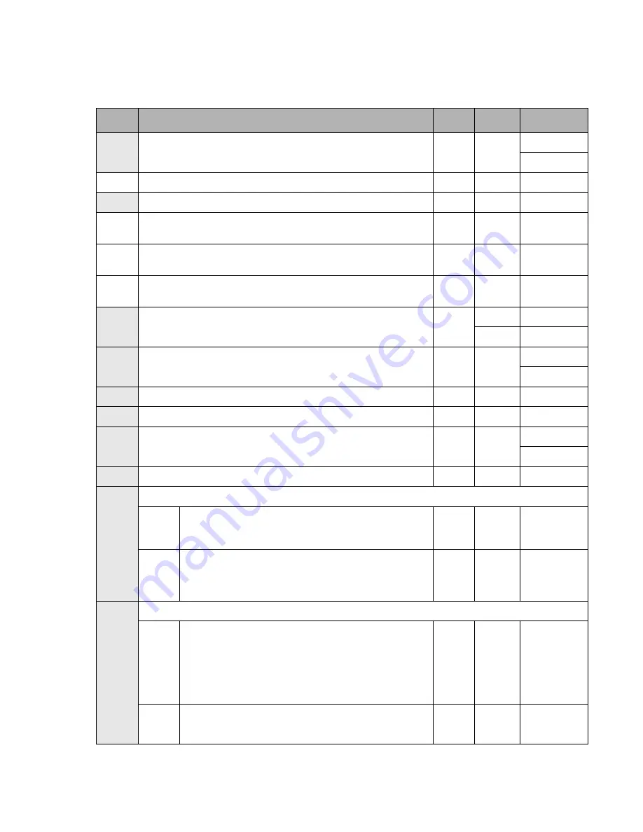
Default is North America. The shaded portions of the table are stored with AT&W command.

Reg

Function

Units

Default

Range

*

S0

Auto answer ring number 

Rings

000

000-255

*JP000-015

S1

Ring counter. Read only.

Rings

000

000-255

S2

Escape character

ASCII

043

000-128

*
*

S3

Carriage return character (CR)

ASCII

013

000-127

*
*

S4

Line feed character (LF)

ASCII

010

000-127

*
*

S5

Backspace character (BS)

ASCII

008

000-032

*

S6

Wait time for dial tone.

sec

002

002-065

*JP 004

*JP004-065

*

S7

Wait time for dial tone.

sec

050

001-255

*JP035-059

*

S8

Pause for dial delay modifier “,”.

sec

002

002-065

*

S10

Carrier loss Disconnect time.

100ms

020

001-255

*

S11

DTMF Dialing speed.

1ms

095

050-150

*JP70-150

S12

Escape prompt delay.

20ms

050

000-255

S14

General bit mapped options status. (Read only)

0:

Enable short form result codes

ATV0

Bit 3

1:

Enable long form result codes.

ATV1

3

0:

10PPS

AT&P0, 
&P1

3

Bit 6

1:

20PPS

AT&P2

S21

General bit mapped options status (Read only)

0:

DTR behavior.

AT&D0

Bits 4, 3

1:

DTR behavior.

AT&D1

2:

DTR behavior.

AT&D2

3

3:

DTR behavior.

AT&D3

0:

DCD behavior.

Bit 5

1:

DCD behavior.

Содержание Stylistic ST4000 Series

Страница 1: ...Stylistic ST4000 Series Tablet PC Technical Reference Guide ...

Страница 2: ...crosoft Corporation All other products are trademarks or registered trademarks of their respective companies Copyright 2002 Fujitsu PC Corporation All rights reserved No part of this publication may be copied reproduced or translated without the prior written consent of Fujitsu PC Corporation No part of this publication may be stored or transmitted in any electronic form without the prior consent ...

Страница 3: ... 6 BIOS Setup Main Menu Options 7 Primary Master Submenu Options 8 Advanced Menu Options 9 IrDA Port Configuration Submenu Options 10 Keyboard Features Submenu Options 11 Video Submenu Options 12 Internal Device Configurations Submenu 13 PCI Configuration Submenu 14 CPU Features Submenu 15 Event Logging Submenu 16 Security Menu Options 17 Hard Disk Security Submenu 19 Owner Information Submenu 20 ...

Страница 4: ...are 46 Battery Pack 46 DC Power Inputs 47 Chapter 6 Installing Hardware Options 48 Installing a PC Card 48 Removing a PC Card 48 Installing Removing a DIMM Module 49 Installing a Memory Module 49 Removing a Memory Module 50 Replacing Installing a Wireless LAN Module 51 Removing a Wireless LAN Module 51 Installing a Wireless LAN Module 52 Appendix A Replacing the IDE Hard Disk Drive 53 Removing the...

Страница 5: ... are listed Chapter 5 Peripheral Interfaces This chapter provides details on peripheral interfaces provided by the Stylistic ST4000 Tablet PC and the Stylistic ST4000 Tablet Dock Chapter 6 System Power This chapter provides information on the Tablet PC s system power hardware Chapter 7 Installing Hardware Options This chapter gives detailed instructions on installing hardware options such as PCMCI...

Страница 6: ...he site address is MSDN Microsoft com The following documents provide information on industry standards supported by the Stylistic ST4000 Tablet PC Advanced Configuration and Power Interface ACPI Specification Revision 1 0 The ACPI was developed by Microsoft Intel and Toshiba to manage device control in order to conserve power The ACPI specification and additional detailed information is available...

Страница 7: ...Hardware Features 1 PC Card Support 1 The Stylistic ST4000 Tablet PC is equipped with a PC Card slot that allows you to install a Type I or II PC Card The PC Card slot is compliant with PC CardBus Standard Release 3 0 and provides support for the following PC Card features Multivoltage 3 3 5 V PC Cards detected automatically CardBus PCI bridge type PC Cards Supports PCIC PC Card I O Card protocol ...

Страница 8: ...ving communications from an infrared keyboard or mouse Note that the infrared keyboard mouse port is a transmit only one direction serial port The IrDA FIR port is used for communications compliant with IrDA Standard Revision 1 1 IEEE 1394 Support 1 The Institute of Electrical and Electronics Engineers Inc IEEE standard 1394 architecture supports a fast external bus that allows transfer rates of u...

Страница 9: ...en version 1 7 5F My T Pen is used to create the on screen keyboard for the ST4000P PenOffice Ver 2 3 1 PenOffice is the handwriting recognition utility used by the ST4000P Pen Configuration applet The pen configuration applet allows you to modify the behavior of the pen To select the My T Pen and PenOffice utilities click Start All Programs and select My T Pen or PenOffice Tools from the list of ...

Страница 10: ...data resides in the system s CMOS memory When the system is powered on BIOS data is copied or shadowed into the system s dynamic memory and the system runs using BIOS parameters stored in dynamic memory BIOS Setup Utility 2 The BIOS Setup Utility is a configuration utility that you can use to change your system s permanent BIOS settings The BIOS Setup Utility application is stored in the BIOS flas...

Страница 11: ...utton the one that is farthest from the application buttons Tap on the menu name in the menu bar Tap on the right or left side of the Select Menu field in the command bar Use the right or left arrow keys on an external keyboard System Time 02 34 56 System Date 10 29 2002 Primary Master TOSHIBA MK2018GAP PM Language English US PhoenixBIOS Setup Utility F1 Help ESC Exit Select Item Select Menu Chang...

Страница 12: ... the command bar Use the and space keys on an external keyboard Access a pop up menu with a list all possible settings for a given BIOS option Tap on the option then tap on the Ent application button Double tap on the setting of your choice to select it Select and enter a submenu To select and enter a submenu do one of the following Tap twice on the submenu name Select the submenu using the up and...

Страница 13: ...at the system time option uses a 24 hour format System Date 01 01 1980 to 12 31 2099 RTC calendar setting in month day year format Primary Master Submenu ___ Select this field to access the primary disk drive submenu See Primary Master Options later in this section Language English Japanese Select the display language for the BIOS System Time 02 34 56 System Date 10 29 2002 Primary Master TOSHIBA ...

Страница 14: ...ctors Display only LBA Mode Control Enabled Display only PIO Transfer Mode Fast PIO 4 Display only DMA Transfer Mode Ultra DMA 5 Display only PhoenixBIOS Setup Utility F1 Help ESC Exit Select Item Select Menu Change Values Space Enter Select Sub Menu F9 Setup Defaults F10 Save and Exit Item Specific Help Select ATA ATAPI drive installed here Auto The BIOS auto types the drive on boot time None The...

Страница 15: ...ure additional device controllers See Internal Device Configurations Submenu Options on page 13 for details PCI Configurations Submenu ____ Enter this menu to reserve specific IRQs for use by ISA devices See PCI Configuration Submenu Options on page 14 for details CPU Features Submenu ____ Enter this submenu to change CPU features See CPU Features Submenu Options on page 15 for details Event Loggi...

Страница 16: ...e the IrDA port in Fast IR mode 4 Mbps IrDA base I O Address IRQ 238 IRQ3 338 IRQ3 Determines the base I O address and interrupt request level used for the infrared port The Infrared Port option must be set to Enabled before this setting can be changed I O Address 400 43F 480 4BF 500 53F 580 5BF Determines the base I O address for the infrared port This option is only selectable when the Infrared ...

Страница 17: ...tions Option Settings Description Numlock Auto On Off This option determines the state of the NumLock key when the system is powered on F1 Help ESC Exit Select Item Select Menu Space Enter F9 Setup Defaults F10 Save and Exit Change Values Select Sub Menu Exit Submenu Item Specific Help PhoenixBIOS Setup Utility Select power on state for Numlock Keyboard Features Numlock Off ...

Страница 18: ...taneous Determines the default display device Select the appropriate option to choose the LCD internal flat panel an external video monitor or both as the default display device Display Internal Flat Panel F1 Help ESC Exit Select Item Select Menu Space Enter F9 Setup Defaults F10 Save and Exit Change Values Select Sub Menu Item Specific Help Select display terminal Video Features PhoenixBIOS Setup...

Страница 19: ...to is selected the LAN device is always enabled when AC power is supplied When running on battery power the LAN device is only enabled when the link is active When Enabled is selected the LAN device is enabled When Disabled is selected the LAN device is disabled Wireless LAN Disabled Enabled When Enabled is selected the optional wireless LAN is enabled When Disabled is selected the optional wirele...

Страница 20: ...d Select Reserved if the IRQ is needed for use by a legacy ISA device F1 Help ESC Exit Select Item Select Menu Space Enter F9 Setup Defaults F10 Save and Exit Change Values Select Sub Menu Item Specific Help Reserve specific IRQs for use by legacy ISA devices PCI Configurations IRQ Reservation PhoenixBIOS Setup Utility Exit Submenu F1 Help ESC Exit Select Item Select Menu Space Enter F9 Setup Defa...

Страница 21: ...e CPU runs at low speed When Max Batt is selected the CPU is throttled depending upon the power source When Automatic is selected the CPU runs at high speed when AC power is supplied otherwise at low speed On AC Max Performance Battery Optimized Max Batt Automatic This option allows you to determine the speed of the CPU when power is applied When Max Performance is selected the CPU runs at high sp...

Страница 22: ... selected for Event Logging When Enabled is selected the event may be logged When Disabled is selected the event is ignored Clear All Event Logs No Yes Choose Yes to clear all DMI event logs at the next boot This setting is reset to No after the event logs are cleared Mark Events as Read Enter Press Enter or press the Enter key to mark all events currently in the event log as read Marked events wi...

Страница 23: ...loppy Disk Access and Hard Disk Boot Sector When enabled a supervisor password or user password if used is required to run BIOS Setup Set User Password Tap on the setting field for this option or press the Enter key to specify a user password Specifying a user password grants access to the following Security menu options only User Password Password On Boot Other Security menu options are not acces...

Страница 24: ...termines who has access to an external floppy drive Select Supervisor Only to allow diskette access only after the system is started by entering a supervisor password when the Password On Boot option is enabled If the Password On Boot option is disabled the floppy drive is not accessible When Supervisor Only is selected the system prevents diskette access if Supervisor Password is enabled and the ...

Страница 25: ... disk is locked it cannot be read on any but the original system or in a system with an identical password F1 Help ESC Exit Select Item Select Menu Space Enter F9 Setup Defaults F10 Save and Exit Change Values Select Sub Menu Main Advanced Exit Submenu Power Savings Exit Item Specific Help PhoenixBIOS Setup Utility Hard Disk Security Primary Master Disabled Disabled The feature is disabled Enabled...

Страница 26: ...Magenta Yellow Bright White Gray Select a color for the foreground Background Color Black Blue Green Cyan Red Magenta Brown White Gray Light Blue Light Green Light Cyan Light Red Light Magenta Yellow Bright White Black Select a color for the background F1 Help ESC Exit Select Item Select Menu Space Enter F9 Setup Defaults F10 Save and Exit Change Values Select Sub Menu Item Specific Help PhoenixBI...

Страница 27: ...tem automatically performs a save to disk operation then powers off when the battery is low Note This feature is supported only by Windows XP and Windows XP Tablet PC edition It should be set to Off for Windows 2000 systems Resume On LAN Off On Select On to configure the system to resume operation when the internal LAN device receives a Magic Packet while it is in Suspend mode Auto Save To Disk Of...

Страница 28: ... screen is displayed If POST errors occur POST messages are displayed regardless of this setting Preboot Execution Environment Disabled Enabled Determines whether to boot up from a network server Select Enabled to allow the system to boot from a network server Preboot Execution Environment If Disabled is selected this feature is disabled Boot Device Priority Submenu Select this submenu to configur...

Страница 29: ...ove to move Hard Disk Drive down you must tap Optical Media Drive to move it above Hard Disk Drive If there is a next to an item tap the item then press the Ent key to expand the list PhoenixBIOS Setup Utility F1 Help ESC Exit Select Item Select Menu Item Specific Help Floppy Disk Drive Hard Disk Drive Optical Media Drive Space Enter F9 Setup Defaults F10 Save and Exit Change Values Select Sub Men...

Страница 30: ...ed in Tablet PC including built in memory Onboard Total memory installed in Tablet PC less any memory in memory slot Memory Slot Total memory installed in Tablet PC memory slot Asset Number System asset number Note The Asset Number is not displayed if user defined string is not stored PhoenixBIOS Setup Utility F1 Help ESC Exit Select Item Select Menu Space Change Values Enter Select Sub Menu F9 Se...

Страница 31: ...Defaults Load default settings for all BIOS Setup options Discard Changes Read previous settings from CMOS memory and load in all BIOS Setup options Save Changes Save BIOS changes to CMOS PhoenixBIOS Setup Utility F1 Help ESC Exit Select Item Select Menu Space Change Values Enter Select Sub Menu F9 Setup Defaults F10 Save and Exit Main Advanced Security Power Boot Info Exit Item Specific Help Exit...

Страница 32: ...et with 8MB shared memory using UMA and DVMT Unified Memory Architecture UMA delivers low power high performance 3D 2D graphics video and display capabilities Dynamic Video Memory Technology DVMT responds dynamically to application requirements and allocates the proper amount of memory 48MB max for optimal graphics and system performance I O Controller LPC47N267 Standard Microsystems Corporation C...

Страница 33: ...acom Pen Weight 0 53 oz 15g Size 5 51 length x 0 35 diameter 140 mm x 9 mm Vendor Wacom Passive Digitizer Stylistic ST4000P Tablet PC Type Resistive digitizer Area 8 27 x 6 28 210 mm x 159 4 mm Resolution 4 096 x 4 096 points Sampling Rate 100 pps Interface Serial interface Vendor SMK Pen Weight 0 35 oz 10g Size 5 53 length x 0 35 diameter 140 5 mm x 9 mm Vendor Pilot Table 3 3 Display Specificati...

Страница 34: ... 4 Environmental Specifications 3 Environmental specifications for the Stylistic ST4000 Tablet PC are given in Table 3 5 Table 3 4 Supported Video Modes for External Monitors Video Configuration Resolution Colors CRT only Max 1600 x 1200 Up to 16 M Simultaneous Max 1024 x 768 Up to 16 M Table 3 5 Environmental Specifications Feature Specification Temperature Operating 41 to 95 F 5 to 35 C Nonopera...

Страница 35: ... external monitor See Table 3 4 Supported Video Modes for External Monitors on page 28 for more details Universal Serial Bus Port USB A Two 2 USB Series A receptacles on Tablet PC IrDA Port Infrared transceiver built into Tablet PC Compliant with IrDA Standard Revision 1 1 Supports FIR 4 Mbps max SIR 115 Kbps max Range approximately 1 M 15 degrees from center Infrared Keyboard Port Infrared receiv...

Страница 36: ...fe Approximately 4 5 hours when running dependent upon application power management and backlight Minimum 5 days in Suspend to RAM mode Approximately 30 days in Fully Off mode Contact layout Charge times are for a 0 charged battery pack charging in Tablet PC not in an external battery charger If the battery pack charge is 90 or higher when you connect DC power the battery pack will not charge thus...

Страница 37: ...59 75mm w x 32 2mm d x 3 5mm h Chip Lucent LU97 AC Link Soft Modem Chipset Data Mode Capability ITU T V 90 ITU T V 34 extended rate V32bis V32 V22bis TIA EIA 602 standard for AT command set V 42 error correction V 42bis and MNP Class 5 data compression Fax Mode Capability ITU T V17 V29 V27ter V21 ch2 TIA EIA 578 Class 1 Fax Support Countries USA Canada Japan Singapore Malaysia UK France Germany Fi...

Страница 38: ... 247 DoC Class B ETSI EN 300 328 ICES 003 Canada RSS 210 Immunity EN55024 1998 ETSI EN 301 489 17 V 1 1 1 2000 9 Safety UL and cUL Listed UL 1950 3rd edition TuV T Mark EN60950 Telecom FCC Part 68 IC CS 03 Table 3 11 Stylistic ST4000 Tablet Dock Specifications Feature Specification Comments DC power input tip sleeve 16 VDC 10 3 75 A External Monitor VGA Port Standard 15 pin video connector System ...

Страница 39: ...ows you to connect the optional Stylistic ST4000 Tablet Dock Pin assignments for peripheral interfaces on the Stylistic ST4000 Tablet PC are given in the following sections Table 4 1 Peripheral interfaces Interface Tablet PC Quantity Tablet Dock Quantity DC Input connector 1 1 Wireless LAN port 1 IEEE 1394 jack 1 1 External Monitor port 1 1 Line Out jack 1 IrDA port 1 Infrared keyboard port 1 Univ...

Страница 40: ...y be necessary to install drivers and application software to support your USB device The Stylistic ST4000 Tablet Dock provides three USB ports Ensure that your USB configuration does not exceed the individual port maximum load on the total system load Note that the conductor gauge and length of your USB cabling will affect the voltage drop and signal propagation between USB devices Refer to the U...

Страница 41: ...when they appear elsewhere Signals provided on the system interface port duplicate signals for connectors on the Tablet PC Do not use peripheral connectors on the Tablet PC when using corresponding interfaces on the system interface port The connectors used for the system interface port are manufactured by Hirose Connector part numbers are EX80 1005 main unit and EX80 100P1 tablet dock side Table ...

Страница 42: ...1 GND Ground 34 GND1 GND Ground for VGA 35 D_VGAB 36 GND1 GND Ground for VGA 37 D_VGAG 38 GND1 GND Ground for VGA 39 D_VGAR 40 GND1 GND Ground for VGA 41 GND1 GND 42 GND1 GND Ground for IEEE 1394 43 D_TPB1 IEEE 1394 44 D_TPB1 45 GND1 GND Ground for IEEE 1394 46 D_TPA1 IEEE 1394 47 D_TPA1 48 GND1 GND Ground for IEEE 1394 49 GND1 GND Ground Table 4 4 Tablet Dock Interface Connector Pin Assignments P...

Страница 43: ...DOCK 62 BAY_LED 63 GND1 GND Ground 64 USB_P3NC 65 USB_P3PC 66 GND1 GND Ground 67 USB_P4NC 68 USB_P4PC 69 GND1 GND Ground 70 USB_P4NC 71 USB_P4PC 72 GND1 GND Ground 73 GND1 GND Ground 74 DOCK_ID0 75 DOCK_ID1 76 GND1 GND Ground 77 ROTATE_SMI 78 GND1 GND Ground Table 4 4 Tablet Dock Interface Connector Pin Assignments Pin Signal Name Level Description Port or Connector ...

Страница 44: ...Ground for AUDIO 87 LOUTL 88 GND1 GND Ground for AUDIO 89 LOUTR 90 GND1 GND Ground for AUDIO 91 GND1 GND Ground 92 RXD 93 RXD 94 NC 95 NC 96 NC 97 TXD 98 TXD 99 GND1 GND Ground 100 DOCK_ON1 Table 4 4 Tablet Dock Interface Connector Pin Assignments Pin Signal Name Level Description Port or Connector ...

Страница 45: ...IrDA or FIR See IrDA Port Configurations Submenu Options on page 10 for details on BIOS options for the IrDA port Table 4 5 IrDA Port Specifications Feature Specification Standard supported IrDA Standard Revision 1 1 Distance Up to 1 meter point to point environmental conditions affect usable range Conveyable wave Infrared rays wavelength peak 875 nm Signal Send data Receive data Modulation Data R...

Страница 46: ...he condition has no effect on the given output Table 4 6 Active Audio Inputs Input Activity Tablet PC Tablet Dock Microphone built in Microphone Input Jack Line Input Jack Microphone On microphone built into Tablet PC Enabled Plug not inserted NA Tablet PC Microphone jack used external microphone connected Disabled Enabled NA Tablet Dock Microphone jack used external microphone connected Disabled ...

Страница 47: ...D11 10 A11 A11 CAD12 11 A9 A9 CAD14 12 A8 A8 CCBE1 13 A13 A13 CPAR 14 A14 A14 CPERR 15 WE WE CGNT 16 READY IREQ CINT 17 VCC VCC VCC 18 VPP1 VPP1 VPP1 19 A16 A16 CCLK 20 A15 A15 CIRDY 21 A12 A12 CCBE2 22 A7 A7 CAD18 23 A6 A6 CAD20 24 A5 A5 CAD21 25 A4 A4 CAD22 26 A3 A3 CAD23 27 A2 A2 CAD24 28 A1 A1 CAD25 29 A0 A0 CAD26 30 D0 D0 CAD27 31 D1 D1 CAD29 32 D2 D2 RFU 33 WP IOIS16 CCLKRUN 34 GND GND GND 3...

Страница 48: ... CTRDY 54 A23 A23 CFRAME 55 A24 A24 CAD17 56 A25 A25 CAD19 57 VS2 VS2 CVS2 58 RESET RESET CRST 59 WAIT WAIT CSERR 60 RFU INPACK CREQ 61 REG REG CCBE3 62 BVD2 SPKR CAUDIO 63 BVD1 STSCHG CSTSCHG 64 D8 D8 CAD28 65 D9 D9 CAD30 66 D10 D10 CAD31 67 CD2 CD2 CCD2 68 GND GND GND 16 bit PC Card Interface CardBus Pin Memory Only I O Memory ...

Страница 49: ... Signal Name 1 1 RESET 2 2 GND 3 3 DATA7 4 4 DATA8 5 5 DATA6 6 6 DATA9 7 7 DATA5 8 8 DATA10 9 9 DATA4 10 10 DATA11 11 11 DATA3 12 12 DATA12 13 13 DATA2 14 14 DATA13 15 15 DATA1 16 16 DATA14 17 17 DATA0 18 18 DATA15 19 GND 20 KEY 21 19 DMARQ 22 20 GND 23 21 DIOW STOP 24 22 GND 25 23 DIOR HDMARDY HSTROBE 26 24 GND 27 25 IORDY DDMARDY DSTROBE 28 26 CSEL 29 27 DMACK 30 GND 31 28 INTRQ 32 29 IOCS16 33 ...

Страница 50: ...ed in the frequency domain TPA to TPB crosstalk 26dB within 1MHz to 500MHz range Signal velocity equal to or less than 5 05ns meter Signal pair attenuation 100MHz 2 3dB 200MHz 3 2dB 400MHz 5 8dB RJ 45 LAN Port 4 P O I N T The IEEE 1394 and USB ports on the Tablet Dock are independent ports i e they are not pass through ports Table 4 10 IEEE 1394 Connector Pin Assignments Pin Signal Remarks 1 TPB T...

Страница 51: ... Monitor Port 4 Table 4 12 External Monitor Port Pin Assignments Pin Signal KB Host I O 1 RED 2 GREEN 3 BLUE 4 NC 5 GND 6 GND 7 GND 8 GND 9 DDCVCC 10 GND 11 NC 12 DDCDATA 13 HSYNC 14 VSYNC 15 DDCCLK 5 4 3 2 1 6 7 8 9 10 11 12 13 15 14 ...

Страница 52: ... battery pack The bridge battery will not power the system in the Fully On state The Tablet PC is equipped with a microcontroller called the power management microcontroller unit PMU which is dedicated to managing battery pack power The battery pack charge is monitored by the PMU The PMU determines the percent of charge remaining in the battery pack controls the battery level and supplies battery ...

Страница 53: ...puts must provide 3 75 amps at a continuous DC voltage of 16 volts 10 Specifications for the DC input connectors on the Tablet PC and Tablet Dock are given below This is the part number for the female DC input connector on the Tablet PC and the Tablet Dock Table 5 1 DC Input Connectors Connector type EIAJ RC 5320A Type 5 Connector vendor Hosiden Vendor part number HEC3900 01 010 Pin assignments Ce...

Страница 54: ...h the arrow on the PC Card facing up insert the card through the shutters in the PC Card slot as shown in Figure 6 1 2 Push the PC Card into the slot until it is seated 3 If necessary install any driver or application software necessary to use your PC Card The PC Card is now installed and you can use the PC Card with your system Figure 6 1 Installing a PC Card Removing a PC Card 6 To remove a PC C...

Страница 55: ...2 Figure 6 2 Accessing the Memory Slot 3 Insert the DIMM module in the socket at an angle and push it down until it locks into place as shown in Figure 6 3 Note that the DIMM module is keyed to prevent it from being inserted backwards Figure 6 3 Installing a DIMM Module 4 Reinstall the cover and screws that you removed in step 2 5 Confirm that the DIMM module is recognized by the system To do so r...

Страница 56: ... is in Suspend mode or running 2 Remove the screws from the cover plate on the back of the Tablet PC and remove the cover plate as shown in Figure 6 2 3 Gently spread the latches on the socket that lock the DIMM module in place until the DIMM module is loose 4 Remove the DIMM module from the socket The DIMM module is now removed from the Tablet PC Refer to Installing a Memory Module on page 49 to ...

Страница 57: ... Antenna Module 9 with the Wireless LAN Module 3 3 Remove the Antenna Module screw 10 4 Carefully unplug the cable connector 6 from the Wireless LAN Module 5 Press the two connector latches 4 5 that hold the Wireless LAN Module 3 away from the module to disengage the module from the latches The front of the module will pop up when it is disengaged 6 Once the module is disengaged pull it carefully ...

Страница 58: ... LAN Module 6 1 If you have a Wireless LAN Module installed in your Tablet PC remove it as directed in Removing a Wireless LAN Module on page 51 2 To install a new Wireless LAN Module follow the instructions in Removing a Wireless LAN Module on page 51 in reverse order ...

Страница 59: ...isk Drive Cover Plate 3 Carefully disconnect the small connector by pulling upwards reference Figure A 2 Use care when disconnecting this connector it is attached to a delicate flex cable C A U T I O N Do not attempt to disassemble or modify the hard disk drive Do not remove any labels from the hard disk drive HDD replacement should only be performed at a static free workstation Avoid touching con...

Страница 60: ...hard disk drive If you are returning the hard disk drive for repair ensure that the packaging material will protect the drive sufficiently during shipment Installing the Hard Disk Drive 6 To install the hard disk drive refer to Figures A 1 through A 3 and perform the following steps 1 Insert the hard disk drive into the Tablet PC 2 Follow the steps contained in the section entitled Removing the Ha...

Страница 61: ...e character after the AT The commands are not case sensitive upper and lower case characters are treated the same All commands should be followed by the CR character stored in S3 Spaces are counted as characters Command indication can be a selected letter or number message or it can be no return message by designation Data format is as follows Note Baud rate and data format are detected by the AT ...

Страница 62: ...and The range of n is 0 3 E 0 Disables echo to the computer 1 Enables echo to the computer 3 H 0 Modem goes on hook 3 1 Modem goes off hook I 0 Returns modem identity string and driver version number same as I3 1 Calculates ROM checksum and displays it on the DTE 2 Performs a ROM check and calculates and verifies the checksum displaying OK or ERROR 3 Returns modem identity string and driver versio...

Страница 63: ...ult Code No Dialtone Busy Code 0 After S6 Displays CONNECT Not displays Not displays 1 After S6 Displays CONNECTXXX Not displays Not displays 2 Wait Dial Tone S6 Displays CONNECTXXX Displays Not displays 3 After S6 Displays CONNECTXXX Not displays Displays 4 Wait Dial Tone S6 Displays CONNECTXXX Displays Displays 3 Z Reset and recall stored user profile C 0 State of the carrier from remote modem i...

Страница 64: ...reak length in 100ms units 3 K 1 Receives break from the DTE when on line mode 5 0 2 4 Enter on line command mode no break set to remote 1 Clear data buffers and send break to remote modem 3 Send break to remote modem immediately 5 Send break to remote modem in sequence with transmitted data 2 On line command mode during a data connection The B is received in order to send a break to the remote 0 ...

Страница 65: ...V 90 Auto Rate 3 2 Attempt to connect at 28000 bit s 3 Attempt to connect at 29333 bit s 4 Attempt to connect at 30666 bit s 5 Attempt to connect at 32000 bit s 6 Attempt to connect at 33333 bit s 7 Attempt to connect at 34666 bit s 8 Attempt to connect at 36000 bit s 9 Attempt to connect at 37333 bit s 10 Attempt to connect at 38666 bit s 11 Attempt to connect at 40000 bit s 12 Attempt to connect...

Страница 66: ... range 0 21 C 0 V 42bis MNP5 disable No data compression 1 V 42bis MNP5 enable Data compression enabled 3 E 0 Disable line quality monitor and auto retrain 1 Enable line quality monitor and auto retrain 2 Enable line quality monitor and fall back fall forward 3 Command Specification Default ...

Страница 67: ...ansmit HDLC data with n carrier Transmit HDLC data modulation 3 FRH n Receive HDLC data with n carrier Receive HDLC data modulation 3 1 000 Data mode 2 0 Data mode 001 Facsimile Class 1 1 Facsimile Class 1 008 Voice Mode 8 Voice Mode 080 VoiceView Mode not supported 80 VoiceView Mode not supported 3 Modulation by parameter 3 V 21 Channel2 300bps 24 V 27ter 2400bps 48 V 27ter 4800bps 72 V 29 7200bp...

Страница 68: ... V 8bis V 18 or V 32bis 6 Enables DCE control of V 8 and CI option v8a 1 The default value disables the CI option while in V 8 negotiation However the modem when answering a call sends the ANSam and is capable of starting in V 34 mode 5 Enables DCE control of V 8 and CI option v8cf 21h c1h Call function for H 324 calls Call function for DSVD calls AT A8E Report current values of subparameter AT A8...

Страница 69: ... time for dial tone sec 002 002 065 JP 004 JP004 065 S7 Wait time for dial tone sec 050 001 255 JP035 059 S8 Pause for dial delay modifier sec 002 002 065 S10 Carrier loss Disconnect time 100ms 020 001 255 S11 DTMF Dialing speed 1ms 095 050 150 JP70 150 S12 Escape prompt delay 20ms 050 000 255 S14 General bit mapped options status Read only 0 Enable short form result codes ATV0 Bit 3 1 Enable long...

Страница 70: ... 7 ATX1 mode dial busy tone detection ATX4 3 0 33 Make Break ratio AT P1 P2 3 Bit 7 1 39 Make Break ratio AT P0 S24 Timer to control sleep mode 000 disable sec 010 000 005 065 S37 Dial line rate 0 Maximum modem speed 3 1 Reserved 2 1200 bits s and 75 bits s 3 300 bits s 4 Reserved 5 1200 bits s 6 2400 bits s 7 4800 bits s 8 7200 bits s 9 9600 bits s 10 12000 bits s 11 14400 bits s 12 16800 bits s ...

Страница 71: ...n maximum modem speed 2 32000 bits s 3 34000 bits s 4 36000 bits s 5 38000 bits s 6 40000 bits s 7 42000 bits s 8 44000 bits s 9 46000 bits s 10 48000 bits s 11 50000 bits s 12 52000 bits s 13 54000 bits s 14 56000 bits s S91 Line Transmit Level This register is effective only for Japan dBm 14 9 15 ...

Страница 72: ...nection at 12000 bits s CONNECT 16800 EC 86 Connection at 16800 bits s CONNECT 300 EC 40 Connection at 300 bits s CONNECT 21600 EC 55 Connection at 21600 bits s CONNECT 24000 EC 56 Connection at 24000 bits s CONNECT 26400 EC 57 Connection at 26400 bits s CONNECT 28800 EC 58 Connection at 28800 bits s CONNECT 31200 EC 59 Connection at 31200 bits s CONNECT 33600 EC 60 Connection at 33600 bits s CONN...

Страница 73: ...4666 EC 104 Connection at 34666 bits s V 90 mode CONNECT 37333 EC 105 Connection at 37333 bits s V 90 mode CONNECT 38666 EC 106 Connection at 38666 bits s V 90 mode CONNECT 41333 EC 107 Connection at 41333 bits s V 90 mode CONNECT 42666 EC 108 Connection at 42666 bits s V 90 mode CONNECT 45333 EC 109 Connection at 45333 bits s V 90 mode CONNECT 46666 EC 110 Connection at 46666 bits s V 90 mode CON...

Страница 74: ...the telephone network or premises wiring using a standard modular jack type USOC RJ 11C which is FCC Part 68 compliant and a line cord between the modem and the telephone network with a minimum of 26AWG The REN is used to determine the number of devices that you may connect to your telephone line and still have all of those devices ring when your number is called Too many devices on one line may r...

Страница 75: ...uirement that the sum of the Ringer Equivalence Numbers of all the devices does not exceed five Avis Aux Utilisateurs Du Réseau Téléphonique Canadien AVIS Le présent matériel est conforme aux spécifications techniques d Industrie Canada applicables au matériel terminal Cette conformité est confirmée par le numéro d enregistrement Le sigle IC placé devant le numéro d enregistrement signifie que l e...

Страница 76: ...T I O N The modem to telephone network connection must be a line cord using a minimum 26 AWG wire W A R N I N G S For continued protection against risk of fire replace only with the same type and rating fuse Danger of explosion if Lithium clock battery is incorrectly replaced Replace only with the same or equivalent type recommended by the manufacturer Dispose of used batteries according to the ma...

Страница 77: ...agnostic messages enabling in BIOS Setup 22 bridge battery 30 C cache specifications 26 cache viewing size of in BIOS Setup 24 connectors DC power input pin assignments 34 CPU speed specifications 26 CPU speed viewing in BIOS Setup 24 current BIOS settings 4 D date changing in BIOS Setup 7 DC power input 34 connector pin assignments 34 connector specifications 47 voltage specifications 29 default ...

Страница 78: ...specifications 30 states 46 power savings BIOS Setup options 21 Q QuickBoot mode enabling in BIOS Setup 22 R related documentation vi removing a DIMM card 50 removing the hard disk drive 53 Replacing Installing a Wireless LAN Module 51 resume on LAN enabling in BIOS Setup 21 S save 21 setup prompt enabling in BIOS setup 22 speaker 40 Specifications 26 specifications AC adapter 31 agency approvals ...

Страница 79: ...tion assignments 34 USB port specifications pen tablet 29 USB port specifications tablet dock 32 user password enabling in BIOS Setup 17 V video memory specifications 26 video modes supported for use with external monitor 28 video external 28 X XVGA video mode 28 ...

Отзывы: