


SK-91F467D-208PFV V1.1
Connectors
FMEMCU-UG-910014-10
- 32 -
© Fujitsu Microelectronics Europe GmbH
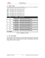
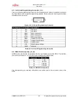
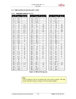
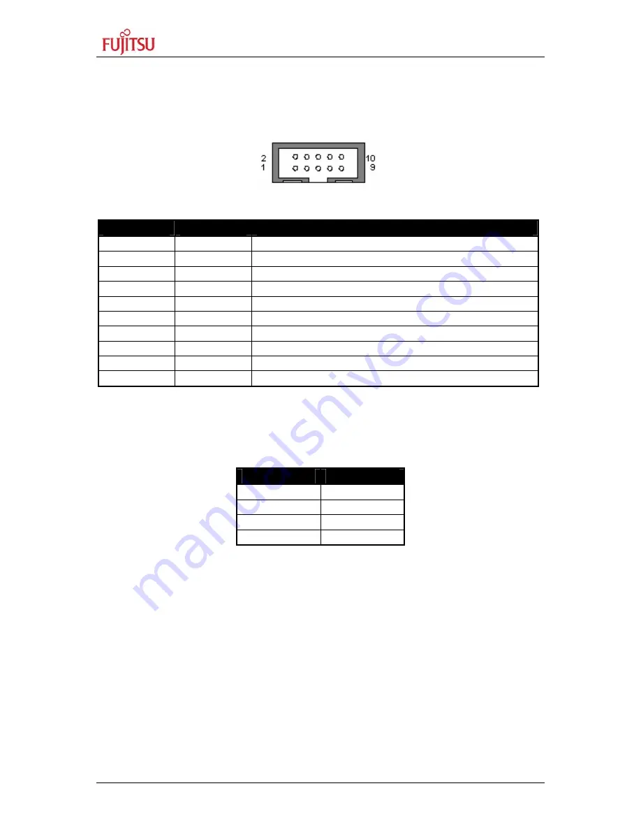
4.5 In-Circuit-Programming
Connector
(X12)
There is a Flash-programming socket on the Starterkit which makes it possible to program
the Flash MCU with a special programming adapter. Mode pins and reset signal are also
available at this connector.
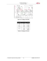
Figure 4-5: In Circuit Programming Connector
Pin Number
Pin Signal
Description
1 NC
Not
used
2 NC
Not
used
3 MD0
MCU
mode-pin
0
4 MD2
MCU
mode-pin
2
5 INITX
MCU
reset
signal
6
SIN4
UART4 receive data
7
SOT4
UART4 transmit data
8 SCK4
UART4
clock
9 VCC
Board
supply
voltage
10 GND
Ground
Table 4-4: In Circuit Programming Connector
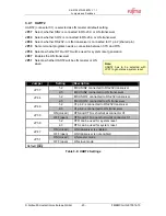
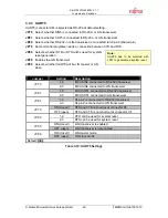
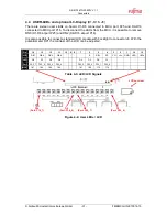
4.6 MCU Pin Connectors (J1-J4)
All MCU pins are directly connected to the four pin header around the MCU. The last two
pins of the pin header J1, J2, J3 and J4 are unused (see PCB silk plot).
Connector
MCU Pins
J1 1-52
J2 53-104
J3 105-156
J4 157-208
Table 4-5: MCU Pin Connectors
The corresponding pin numbers of the MCU are written next to the connector pins on the
PCB.