background image

5. Desktop Stand  (Model P-42TT11)

You need two strong cords.

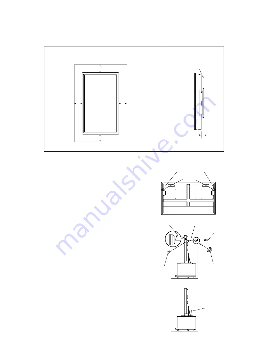
(1) Attach a bracket to each hole at the rear of the

display.
To do this, use screw A (10mm long) to attach
safety bracket A, supplied with the display, to the
hole at the rear of the display.

(2) Attach two brackets to the wall.

To do this, use screws B (20mm long) to attach
safety brackets B, supplied with the display, to the
wall.

∗ 

To make sure that the display is stable, attach

wall brackets at the same height as 

(or slightly lower than) the display brackets.

(3) Tie brackets A and B together

To do this, use strong cords to fasten the display
securely to the wall.

Use the two screws supplied with the stand to
fasten the display using the holes provided at the
rear of the stand.

See the stand (P-42TT11 type) instruction manual
for more information.

– 25 –

When using the wall-mounting unit  (Vertical type)

(cm)

(cm)

10

10

10

10

Left

Right

Upper

Lower

1.5

Wall

Wall mounting unit

Front

Side

Safety bracket A

Screw A

Screw A (10mm)

Safety
bracket A

Safety
bracket B

Screw 
(supplied with stand)

Strong cords  (not supplied)

Screw B (20mm)

Содержание Plasmavision PDS4214W-S

Страница 1: ...PDS4214W S Copy Prohibited FUJITSU GENERAL Proprietar y ...

Страница 2: ...6 7 million 256 each for R G B Audio input 2 pin terminals one system 500mVrms 22k Speaker output 2 built in speakers 1W 1W R L Lever terminal 7W 7W R L 8 Language English German French Italy Spanish Portugese E type Russian Dimensions Width 103 5cm 46 7inch Height 64 0cm 25 2inch Depth 8 5 cm 5 9inch Net weight 31 5kg Environment Operating Temperature 0 to 40 C Relative humidity 20 to 90 Pressure...

Страница 3: ...S 4 SETTING SIGNALS 5 CONNECTION 7 OPERATION AND ADJUSTMENT 8 TROUBLESHOOTING 11 VOLTAGE OF EACH CONNECTOR 19 VS AND VY ADJUSTMENT 20 GENERAL CONNECTION DIAGRAM 21 INSTALLATION 22 DISASSEMBLY 29 PARTS LIST 46 TRANSPORTATION AND HANDLING RESTRICTIONS 48 1 ...

Страница 4: ...sible injury to the operator When transporting by car place the unit as shown in the figure Slots and openings in the cabinet are provided for ventilation These ensure reliable operation and protect the unit from overheating These openings must not be blocked or covered The openings should never be blocked by placing the unit on a bed sofa rug or similar surface The unit should not be placed in a ...

Страница 5: ...r or parts with the same characteristics as the original parts Unauthorized substitutions may result in fire electric shock or other hazards Upon completion of any service of repairs ask the service technician to perform safety checks to determine that the unit is in proper operating condition Place the unit more than one foot away from heat sources such as radiators heat registers stoves and othe...

Страница 6: ...cy of the input signal is 75Hz or less for SVGA and 60Hz for XGA Display dots x lines Horizontal frequency kHz Vertical frequency Hz Signal 852 x 480 31 72 59 97 When a dedicated graphics card used 640 x 480 31 47 59 94 VGA 640 x 480 37 86 72 81 VGA 72Hz 640 x 480 37 50 75 00 VGA 75Hz 640 x 480 43 27 85 01 VGA 85Hz 720 x 400 31 47 70 09 VGA 400 lines 640 x 400 37 86 85 08 VGA 400 lines 800 x 600 3...

Страница 7: ...Connection to PC To video output terminal To S video output terminal To sound output terminal To display analog RGB output terminal To display analog RGB output terminal To RS 232C output terminal To color difference output terminal 7 CONNECTION Terminal Connector VIDEO INPUT BNC S VIDEO INPUT S terminal COMPONENT VIDEO BNC x 3 RGB 1 INPUT mD sub 15P RGB 2 INPUT BNC x 5 AUDIO INPUT Pin jack RS 232...

Страница 8: ...control signal receiver e Main power SW indicator r Power button ON OFF t Input mode selector button y Wide screen selector button u Menu button i Volume adjustment buttons o Adjustment buttons 0 Enter button The remote controller comes with a strap This strap can be attached to the hole at the bottom of the remote controller q Power ON button w Power OFF button e RGB mode selector button r VIDEO ...

Страница 9: ... temperature of unit Main Digital PCB Temp sensor PCB 1 OSD LED lamp display status Cause Check point Steady light Red Stand by status Continuous Flashes continuously Red No power Power supply protector operated AC DC power unit DC DC power PCB PDP panel 1 time Flashes once in 3 sec Red Fan protector operated Fan AC DC power unit DC DC power PCB Main Digital PCB 2 times Flashes twice in 3 sec Red ...

Страница 10: ...nal The ACON signal indicates whether or not AC is supplied The relay signal is output when the ACON signal is H CN103 Power supply unit Ground No NAME SPEC 1 Vpr 5V 4 8 to 5 2V w 7 Vcc 2 24V 23 7 to 24 3V w 1 Power Supply Unit PFW 422 2 DC DC Power PCB CN49 Power supply unit Ground No NAME SPEC 1 Vcc 1 5V 4 8 to 5 2V w 3 Ve 15 52 to 16 48V w 10 Vs 165 0 to 185 0V w CN50 Power supply unit Ground N...

Страница 11: ...n the wide mode Adjustment Adjust Vs and Vy in the no signal state Black picture Test and adjustment points Refer to the drawing below Adjustment value Within 0 1V of the voltage indicated on the label on the PDP unit Power Supply Unit Vy adjustment VR RV210 Vs adjustment VR RV203 Vs test point Vy test point CN42 pin 1 PFW 422 C331 Vs Vs RV210 CN41 RV203 T 6 ...

Страница 12: ...CC1 GND VCC1 VE GND VE VA GND VA 6 1 VCC1 GND VCC1 VE GND VE VA GND VA 6 1 VCC1 GND VCC1 VE GND VS GND VS GND VS GND VS NC VS VS 10 1 VCC1 GND VCC1 VE GND VS GND VS GND VS GND VS NC VS VS 10 1 R 8 G 8 B 8 GND H V GND 68 1 RESET CE CLK DATA GND 5 1 L L GND R GND R L 1 2 GND L 2 L 1 R 1 2 GND R 2 R 1 10 1 GND A5V GND 14V PRI GND D5V D3 3V 5V 10 1 GND 14V 2 1 RESET CE CLK DATA GND 5 1 L L GND R GND R...

Страница 13: ...optical filter may peel off Wipe the surface of the optical filter with a soft lint free cloth such as cotton The surface of the optical filter scratches easily so do not rub or hit it with a hard object 7 The brightness and contrast of the PDP are still inferior to those of a CRT Also note that the ambient light may cause the screen become white and difficult to read Therefore it is recommended t...

Страница 14: ...Power PCB Noise Filter Sirocco Fan R Sirocco Fan L Fan motor R Fan motor L Frame Panel MID Upper Main Digital PCB Frame Panel MID Lower Frame Panel MID Upper Temp Sensor PCB Power Cover Duct Fans Rear Case Lower Power Supply Unit Frame Panel MID Lower Rear Case Upper Front Case Rear Case Lower Optical Filter Key Switch Assy Video PCB PDS4213 4214 Video PCB Unit 1 7 3 12 4 8 11 10 3 6 9 13 to 14 2 ...

Страница 15: ...ver Stand R 8108585009 Cover Terminal 8110299000 Holder Filter T B 8110614001 8109903000 Holder Filter L R 8110619006 8109904007 Key Switch unit Holder Key switch 8107744001 Plate Key switch 8110793003 8110794000 Cover Key switch 8107743004 Spring Key switch 8108316009 Holder damper 8110122001 Damper Key switch 8109047001 Latch Key switch 8108703007 Button Key switch 8107745008 Key Switch PCB Assy...

Страница 16: ...ON AND HANDLING RESTRICTIONS Transportation Don t load the plasmavision on a truck as shown in the drawing Don t hold the surface of the optical filter Over 30 cm Drop Floor Bad loading Handling Never drop Never topple ...

Страница 17: ... 49 Don t stack the plasmavision over three units high Load the plasmavision as shown above Example of good transportation and handling Good loading 3 4 ...

Страница 18: ...MEMO ...

Страница 19: ...August 2000 Printed in Japan 0008J1729 ...

Страница 20: ...2 8110545022 8110545022 8110545022 LED Photo PCB Assy 8110754011 Power Supply Unit PFW 422 8108193006 DC DC Power PCB M8KR 8110809018 Audio PCB Assy 8110592026 Temp Sensor PCB 8110756015 PDP Panel 8110753007 FPF42C10660UE 41 Optical Filter 8110688002 8105046145 Fan Motor Small 8900243015 Sirocco Fan 8900242025 Adapter Main SW 8110620002 Power Cord VDE 8108106006 UL CSA 8108105009 8105865005 SAA 81...

Страница 21: ... 30 1 Removing the Video PCB Unit 1 Remove the 7 screws 2 Pull out the Video PCB Unit 3 Remove the 10 screws from the Video PCB Unit 4 Remove the Video PCB Assy Video PCB Unit Video PCB Assy ...

Страница 22: ...Temp Sensor PCB 1 Remove the Rear Case Upper 2 Remove the connector and screw 4 Removing the DC DC Power PCB Assy 1 Remove the Rear Case Upper 2 Remove the insulation sheet on the DC DC Power PCB 3 Remove the connectors and the 3 screws Do not lose the screw assy View after Rear Case Upper removed View after insulation sheet removed ...

Страница 23: ...Cover stands on the bottom and remove the screws in the hole 2 Lift the bottom of the Bezel Front while pressing the main power button and move the Bezel Front upward the upper side to remove it The topside of the Bezel Front is hooked Bezel Front ...

Страница 24: ... 1 See the drawing below for the number and positions of the screws 2 2 Remove by sliding the Holder Filters in the arrow directions View after Bezel Front removed Screw fixing position 4213 4214 series Fix the screws indicated by the marks only 14 pcs Unmarked positions show that screws are not used ...

Страница 25: ...emove the Video PCB Unit 3 Remove the Frame Panel MID Lower Remove the 3 screws 4 Remove the 7 screws at the input terminals 5 Remove the 5 screws at the shield bracket of the Main Digital PCB Assy 6 Remove the shield bracket and connectors and remove the screw View after Rear Case Upper removed ...

Страница 26: ...Audio PCB 1 Remove the Rear Case Upper 2 Remove the Frame Panel MID Lower Remove the 3 screws 3 Remove the 2 screws at the audio output terminals 4 Remove the connectors and the 3 screws View after Rear Case Upper removed ...

Страница 27: ... 36 9 Removing the Noise Filter AC inlet 1 Remove the Rear Case Upper 2 Remove the 3 wire connectors and the 2 screws View after Rear Case Upper removed ...

Страница 28: ...ove the Rear Case Upper 2 Remove the Temp Sensor PCB 3 Remove the Frame Panel MID Upper 4 Remove the Power Cover Refer to steps 1 to 4 of 12 Removing the Power Supply Unit 5 Remove the 2 screws and connectors View after Rear Case Upper removed ...

Страница 29: ...oving the Sirocco Fan 1 Remove the Rear Case Upper 2 Remove the Frame Panel MID Upper 3 Remove the Duct Fan Unhook the 3 hooks on the Duct Fan 4 Remove the Sirocco Fan Remove the 2 screws and connectors Top view ...

Страница 30: ...it 1 Remove the Rear Case Upper 2 Remove the Temp Sensor PCB 3 Remove the Frame Panel MID Upper Remove the 4 screws 2 long 2 short 4 Remove the Power Cover Unhook the 4 hooks on the Power Cover View after Rear Case Upper removed Top view ...

Страница 31: ...und wire 5 Remove the Power Supply Unit 5 1 Remove the screw holding the ground wire 5 2 Remove the connectors and the 6 screws 5 3 Remove the small PCB first Replace the Power Supply Unit on a couple of PCBs ...

Страница 32: ...ircled in the picture 7 Disconnect the connector to the Power Supply Unit and inlet 8 Remove the Rear Case Lower Remove it together with the Main Digital PCB Audio PCB and Noise Filter Remove the 13 screws View after Video PCB Unit and Rear Case Upper removed Audio PCB Connector for speaker Noise filter Disconnect the black and white wires Main Digital PCB Disconnect the 68 pin connector and other...

Страница 33: ...se 11 1 Install the Frame Panel MID Upper using the 2 screws 11 2 Install the 2 screws jigs to the PDP Panel Unit 11 3 Have two peoples hold the screw jig and the Frame Panel MID Upper and remove the PDP unit from the Front Case 10 Remove the Frame Panel from the Frame Case 10 1 Remove the 6 screws on the Frame Panel Bottom 10 2 Remove the 3 screws on the Frame Panel Top ...

Страница 34: ... 43 14 Removing the parts on the PDP 1 Remove the Power Supply Unit 1 1 Disconnect the 11 connectors 1 2 Remove the 6 screws This picture is in up and down Vertical view ...

Страница 35: ... 44 2 Remove the Frame Panel Top together with Holder Fan L and R Remove the 7 screws 3 Remove the Frame Panel Bottom Remove the 5 screws Frame Panel Bottom Holder Fan R Frame Panel Top Holder Fan L ...

Страница 36: ...emove the X SUS PCB shield Remove the 2 screws and the 68 pin connector 5 Remove the Y SUS PCB Heat Sink 6 Replace the bracket between the defective panel and the new panel Y SUS PCB Heat Sink X SUS PCB Shield ...

Страница 37: ...3 Grounding should be performed Ground connected to power outlet is acceptable 4 Sufficient passage space 5 Installation should be performed by at least two peoples A simple lifter should be used 6 When carrying the unpacked unit do not hold the Optical Filter 3 Outline Drawings Ceiling Floor 64 cm 42 Plasmavision Sufficient space is needed for people to pass or to move objects 94 5 103 5 54 4 64 ...

Страница 38: ...ent the power and other cables from being accidentally pulled make sure that they run along the wall or through corners The display can be installed with either of its sides facing down 24 When using the stand cm cm 10 10 10 6 Left Right Upper Floor Wall 1 5 Floor Front Side When using the wall mounting unit Horizontal type cm cm 10 10 10 6 Left Right Upper Lower 1 5 Wall Wall mounting unit Front ...

Страница 39: ...brackets at the same height as or slightly lower than the display brackets 3 Tie brackets A and B together To do this use strong cords to fasten the display securely to the wall Use the two screws supplied with the stand to fasten the display using the holes provided at the rear of the stand See the stand P 42TT11 type instruction manual for more information 25 When using the wall mounting unit Ve...

Страница 40: ... hole ø30 4 14x25 Oval hole 200 300 200 300 Dimensions Unit mm General view Unit mm Floor Pipe Ornamental adapter Flange Ceiling board Ceiling C installment height 156 0 Flange pipe length B interior ceiling size A Size of the opposite side of ceiling Center of display Selection of pipe length x Unit mm Set name Pipe length X Combined length S 0400 a b 1 400 1 500 1 450 1 550 A 0600 a b 1 600 1 70...

Страница 41: ...lay Hole position caution Screw A M5 screw with washer 2 each Screw A M5 screw with washer Fixing fitting Suspension fitting e Hanging on the Wall Mounting Unit Suspension fitting Screw B Shaft L 30cm Wall r Cabling Display Fasten at the lowest position of the oval hole t Fastening the display Display Shaft fixing fitting L Fixing fitting Shaft fixing fitting R Screw C M4 screw with washer 2 each ...

Страница 42: ...y installation angle of 0 to 5 horizontal and vertical installation For a display installation angle of 5 to 15 horizontal installation only For an angle of 0 to 5 fasten at two places the arm mounting screws A and the lock fitting mounting screws C 4 places on both sides For an angle of 5 to 15 fasten only at the arm mounting screws B 2 places on both sides Remove the lock fitting mounting screws...

Страница 43: ... Check 2 Blinks twice Power turned off after 10 sec RED Check 3 Blinks four times Power not turned off LED blinks only RED Replace Main Digital PCB Assy Blinks five times Power not turned off LED blinks only RED Replace video PCB Assy On screen display normal Check 4 All input images faulty Signal processing PCB faulty Replace Main Digital PCB Assy Video input image faulty Check 5 S video input im...

Страница 44: ...ector CN103 to DC DC power PCB 2 Connect pin 5 of P503 to pin 2 of P502 on DC DC power PCB 3 Disconnect all connectors on DC DC power PCB except P501 4 Turn on main power and power switch Replace PDP Vs and Vy must be adjusted Yes No Does lamp change to green Power Supply circuit faulty Replace Power Supply Unit Vs and Vy must be adjusted No Is voltage at each connector on Power Supply unit normal...

Страница 45: ...ce DC DC power PCB Power Supply Unit circuit faulty Replace Power Supply Unit Temperature protector operated Power lamp Flashes intermittently twice in red for 0 5 sec at an interval of 3 sec Check 3 Start Adjust PDP unit installation so that peripheral temperature is 40 0 C or less No Yes Is ambient temperature of PDP unit less than 47 C Microcomputer peripheral circuit faulty Yes Replace Main Di...

Страница 46: ... Unit No Yes Is voltage at each connector on DC DC power PCB normal DC DC power circuit faulty Replace DC DC power PCB Assy Yes No Is picture displayed normally when PDP changed PDP panel faulty Replace PDP panel Signal processing circuit faulty Replace Main Digital PCB Assy Start Yes No Can this unit select only RGB 1 or RGB 2 mode Install video PCB Assy firmly Yes Is picture displayed on screen ...

Страница 47: ...o Video PCB Unit faulty Replace Video PCB Assy Yes No Are brightness and color difference signals connected to input terminals correctly Check connection cable Yes No Is signal input level normally Signal processing circuit faulty Replace Main Digital PCB Assy Check input signal SYNC signals are added to the Y signal Is picture displayed on screen normally when new video PCB Unit installed ...

Страница 48: ...ve Is horizontal sync signal input to pin 3 and vertical sync signal input to pin 4 of RGB signal Check connection cable Check input signal Connect RGB cable to terminal Check input signal No Change sync switch TTL ANALOG Make sync signal polarity output from signal source negative or make output impedance TTL Note If the synchronizing signal cannot be identified by TTL level measure it in the 75Ω...

Страница 49: ...erminal is connected for audio cable Does 14V appear on CN4 pin w on Audio PCB DC DC power PCB circuit faulty Replace DC DC power PCB Assy Select correct Audio input terminal Is audio input terminal of menu selected correctly for connected audio terminal number Is External speaker of sound menu selected Which speaker is used Select necessary speaker Audio circuit faulty Connect audio cable correct...

Страница 50: ...ss 6 to 6 Position Balance 10 to 10 Speaker Internal External or OTHERS OSD On Off Vertical Position Language English German Spanish or VOL 40 French Italian Width Portugues 20 Monitor No 0 1 2 or 3 Height 0 4 Video mode AUTO NTSC PAL or SECAM N PAL M PAL 4 43 NTSC AGC On Screen Function Off Off saver Time 1H Mode Bluish On Moving Standard white Off area Wide Narrow Status Monitor No Speaker Input...

Страница 51: ...t 4 0 Vertical sync 2 to 1 Clamp pulse 0 to 8 or Status Monitor No Speaker Input priority Off Video S video Comp video Freq scan Input signal Frequency fH fV Preset No Audio input RGB 1 1 2 or RGB 2 No audio Video Extended Enter OSD rotate Normal S video menu Return 90 Deg Comp video 90 Deg Studio mode Off DPMS Off On 1 min 3 min White peak Execute 5 min level Original 10 min calibration Cancel 30...

Страница 52: ...ideo mode The dedicated graphics card is optional In the 800 x 600 and 1 024 x 768 modes images of reduced size are displayed on the screen using size reduction and interpolation Also note that on screen information is also displayed in reduced size Out of range appears if the display receives a signal whose characteristic does not fall within the display s permissible range You can check the inpu...

Отзывы: