Removing and installing components during servicing
Preparing to remove components
If you are going to remove or change system components, prepare for the removal as follows:
Please observe the safety information in chapter
"Important notes", Page 13
.
Remove the power plug from the mains outlet !
►
Switch the device off.
The device must not be in energy-saving mode !
►
Close the LCD screen.
►
Remove all the cables from the device.
►
Turn the device over and place it on a stable,
fl
at and clean surface. If necessary, lay an
anti-slip cloth on this surface to prevent the device from being scratched.
►
Remove the battery (see
"Removing a battery", Page 34
).
Installing and removing memory expansion
Memorymodule
Mainmemory
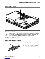
Removing memory
Systemexpansion
Systemexpansion
If you are asked by the Hotline/Service Desk to remove and install the memory
expansion yourself, proceed as follows:
Please observe the safety information in chapter
"Important notes", Page 13
.
When installing/removing memory modules, the battery must be removed from
the notebook and the notebook must not be connected to the power supply,
see
"Preparing to remove components", Page 72
.
Only use memory expansion modules that have been approved for your
notebook (see
"Technical data", Page 88
).
Never use force when installing or removing a memory extension.
Make sure that foreign objects do not fall into the memory extension compartment.
You must open the service compartment to remove or install a memory module. On some devices,
opening the compartment may expose other components. These components should be removed
and replaced only by authorised specialists. Therefore, be sure to observe the following:
Individual components can become very hot during operation. Therefore, we
recommend that you wait one hour after switching off the notebook before removing
or installing memory modules. Otherwise, there is a risk of suffering burns!
As some components are exposed that are sensitive to static electricity, please take
note of chapter
"Notes on installing and removing boards and components", Page 71
.
72
Fujitsu Technology Solutions
Содержание Lifebook E751
Страница 1: ...System Operating Manual LIFEBOOK E751 ...
Страница 3: ......
Страница 15: ...Ports and operating elements Rear 1 2 1 Serial port 2 LAN port Fujitsu Technology Solutions 11 ...

