49
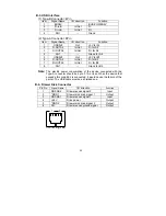
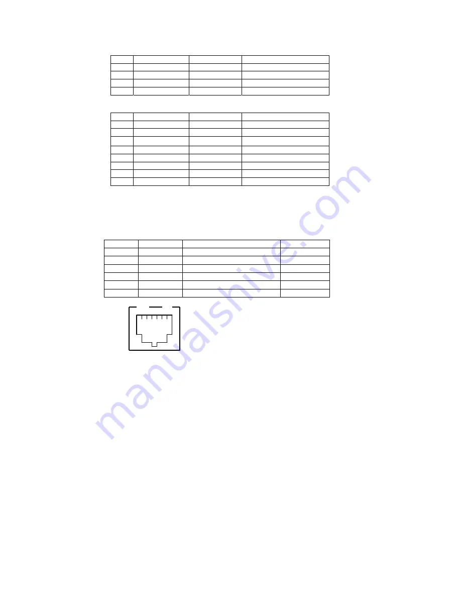
B-3. USB Interface
(1) Type-B Connector: 4Pin
Item
Signal Name
I/O direction
Function
1 BUS5V
-- BUS-POWER5V
2 D-inB
In/Out
D-
3 D+inB
In/Out
D+
4 SG1
-- Grand
(2) Type-A Connector: 8Pin
Item
Signal Name
I/O direction
Function
1
USB5V2
Out
+5V for A1
2
D-OUTA2
In/Out
D- for A2
3 D+OUTA2
In/Out D+ for A3
4
SG1
--
Grand for A4
5
USB5V3
Out
+5V for B1
6
D-OUTA3
In/Out
D- for B2
7
D+OUTA3
In/Out
D+ for B3
8
SG1
--
Grand for B4
Note:
The electric power consumption of the device connected with the
Type-A connector should be up to 0.1A or less. When the device that
exceeds this condition is connected, it would cause the failure of the
printer. The USB cable must be a shielded one.
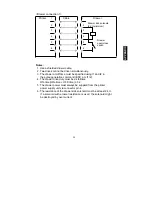
B-4. Drawer Kick Connector
Pin No.
Signal Name
I/O direction
Function
1
DRSNS2
Drawer sense signal 2
Input
2
*DRD1
Drawer kick drive signal 1
Output
3
DRSNS1
Drawer sense signal 1
Input
4 +24V
Drive
power
Output
5
*DRD2
Drawer kick drive signal 2
Output
6
SG
Drawer sense ground signal
Output
Connecting side
1
6
Содержание FP-410
Страница 1: ...THERMAL PRINTER FP 410 USER S MANUAL X0KA02001 Y911 02 ...
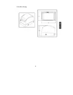
Страница 41: ...40 7 Outline drawing APPENDIX ...


