background image

● 

4 - 10

CAUTION

Do not look directly at the light source during the read operation.

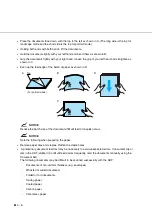
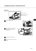
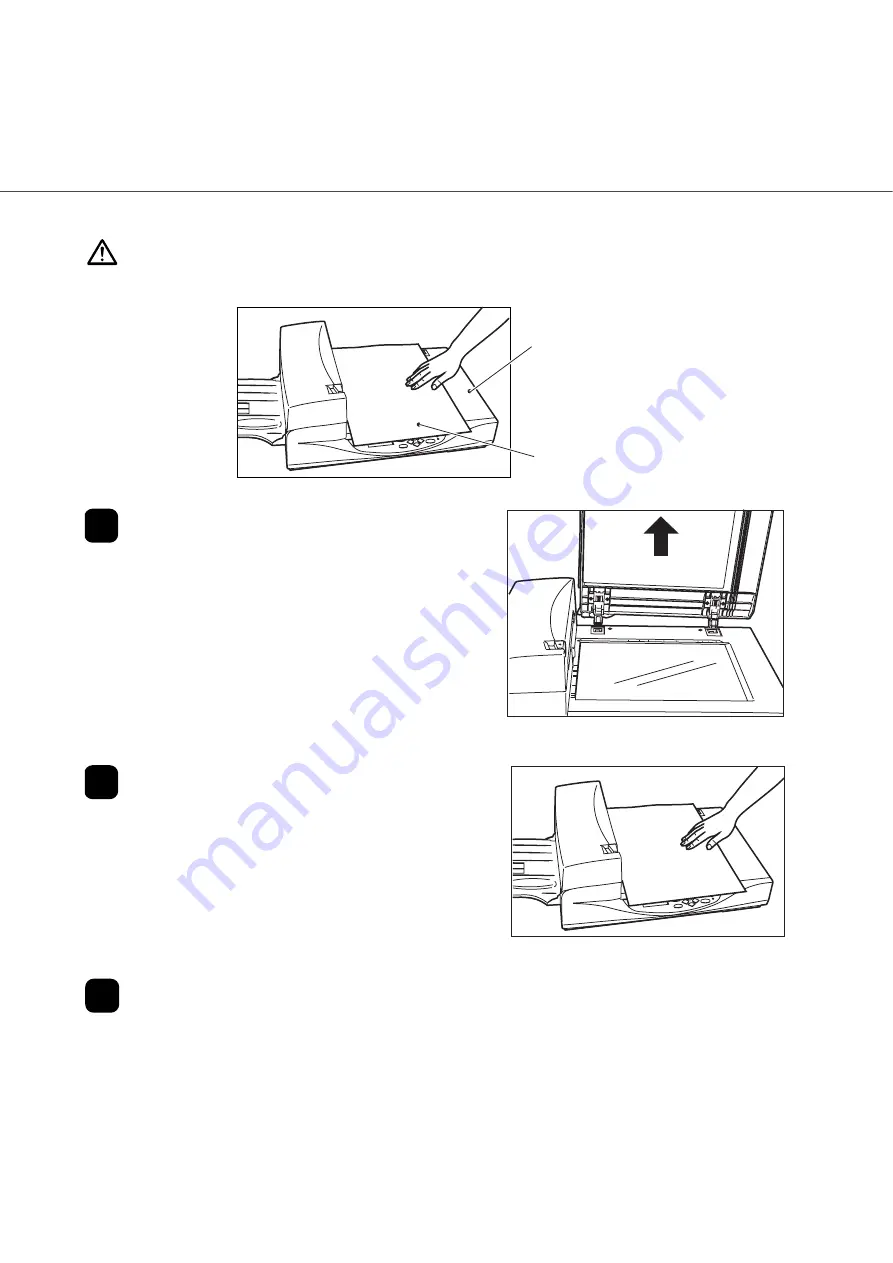
Open the Document cover to an angle of 

approximately 90 degrees, and lift up the 

cover (in the direction of the arrow) to 

remove it.

Place the document face down on the 

Document bed. Issue the read command 

from the host system.

After the read operation, remove the 

document, re-attach the Document cover 

and close it gently.

Document

Document bed


!

Loading Documents Larger than the Document bed

Содержание fi-4340C

Страница 1: ...fi 4340C Image Scanner Operator s Guide ...

Страница 2: ......

Страница 3: ...ment off and on the user is encouraged to try to correct the interference by one or more of the following measures Reorient or relocate the receiving antenna Increase the separation between the equipment and receiver Connect the equipment into an outlet on a circuit different from that to which the receiver is connected Consult the dealer or an experienced radio TV technician for help FCC warning ...

Страница 4: ...ung mit den Bestimmungen der EN45014 CE funkentstört Maschinenlärminformationsverordnung 3 GPSGV Der höchste Schalldruckpegel beträgt 70 dB A oder weniger gemäß EN ISO 7779 International ENERGY STAR Program As an ENERGY STAR Partner PFU LIMITED has determined that this product meets the ENERGY STAR guidelines for energy efficiency The International ENERGY STAR Office Equipment Program is an intern...

Страница 5: ... this product by the user in high safety applications and for any claims or compensation for damages by the user or a third party About the use of mercury To avoid unexpected injury read the following carefully Doing the following actions may result in serious personal injuries Do not put the substance contained in the lamp in your mouth as it has mercury Do not incinerate crush or shred the lamps...

Страница 6: ...he general term Windos is used Manufacturer PFU LIMITED Image Products Sales Dept Imaging Products Division Products Group Solid Square East Tower 580 Horikawa cho Saiwai ku Kawasaki shi Kanagawa 212 88563 Japan Phone 81 44 540 4538 All Rights Reserved Copyright PFU LIMITED 2006 The contentss of this manual may be revised without prior notice No part of this manual may be reproduced in any form wi...

Страница 7: ...com FUJITSU ITALIA S p A Via Nazario Sauro 38 20099 Sesto San Giovanni MI Italy Phone 39 02 26294 1 Fax 39 02 26294 201 Website http www fis fujitsu com E mail mbarondi fis fujitsu com FUJITSU ESPAÑA Services S A U Camino Cerro de los Gamos 1 28224 Pozuelo de Alarcon Madrid Spain Phone 34 91 784 9000 Fax 34 91 784 9379 Website http es fujitsu com E mail info mail fujitsu es FUJITSU AUSTRALIA LTD F...

Страница 8: ...eneral 603 8318 3700 query 603 8318 3700 ext 375 Fax 603 8318 8700 Website http www fujitsu com my E mail WriteToUs fms my fujitsu com FUJITSU PHILIPPINES INC 2 F United Life Building 837 A Arnaiz Avenue Pasay Road Legaspi Village Makati City 1229 Philippines Phone 63 2 812 4001 Fax 63 2 817 7576 Website http ph fujitsu com Imaging Business Division PFU LIMITED Solid Square East Tower 580 Horikawa...

Страница 9: ...bility to any party for any damage caused by errors or omissions or by statements of any kind in this manual its updates or supplements whether such errors are omissions or statements resulting from negligence accidents or any other cause PFU further assumes no liability arising from the application or use of any product or system described herein nor any liability for incidental or consequential ...

Страница 10: ...tains a Glossary of Terms and an Index Refer to the Cleaning and Maintenance Guide for information about the routine operation of the fi 4340C The Cleaning and Maintenance Guide contains chapters on OPERATING INSTRUCTIONS CLEANING REPLACEMENT OF PARTS ADJUSTMENT and TROUBLESHOOTING The fi 4340C is a very fast and highly functional color image scanner developed for high quality color image processi...

Страница 11: ...ot perform repairs on this scanner Contact the store where you purchased the scnner or an authorized FUJITSU Image Sanner service provider to make repairs to this product A TRIANGLE symbol indicates that special care and attention is required The drawing inside the triangle shows the specific caution A CIRCLE with a diagonal line inside shows action which users may not perform The drawing inside o...

Страница 12: ...ower cable may result in fire or electric shock Do not place heavy objects on power cables or pull bend twist heat damage orr modify power cables Also do not use damaged power calbes or power plugs or when the wall socket is loose Use only the specified power cable or connector cables Failure to use the correct cables might cause electric shock and equipment failure Use this scanner only at the in...

Страница 13: ...nd then disconnect its power plug Make sure that the smoking has stopped and then contact the store where you bought the scanner or an authorized FUJITSU scanner service provider Do not insert or drop metal objects into the scanner Do not scan wet documents or documents with paper clips or staples Do not splash or allow the scanner to get wet If foreign objects water small metal objects liquids et...

Страница 14: ... Before moving the scanner be sure to disconnect the power plug from the power outlet and disconnect data cables Also make sure that the floor is free of obstructions If the equipment is dropped or covers etc have been damaged switch power supply OFF remove the plug from the socket and call your dealer or maintenance service center Do not place the scanner where liquid spills may occur Do not touc...

Страница 15: ... scanner on a strong surface that will support the weight of the scanner and other devices Firmly insert the power plug into the power outlet as far it can go Do not block the ventilation ports Blocking the ventilation ports generates heat inside of the scanner which may results in fire or scanner failure Do not place heavy objects on the scanner or use the scanner s top surface for performing oth...

Страница 16: ...Also protect the scanner from static electricity as this might cause the scanner to malfunction You may get injured if your clothing neckties or hair etc is entangled in the moving components such as gears and rollers When the scanner is not used for a long period of time be sure to disconnect the power plug from the power outlet for safety Do not install the scanner in the direct sunlight or near...

Страница 17: ...ts on the ADF 4 5 Loading Documents on the Document bed 4 9 Loading Documents Larger than the Document bed 4 10 Reading a Page from a Thick Book 4 11 CHAPTER 5 ADF DOCUMENT SPECIFICATION 5 1 Document Size 5 2 Document Quality 5 3 Maximum ADF Capacity 5 5 Areas not to be Perforated 5 6 Grounding Color Areas 5 7 Multi Feed Detection Conditions 5 8 Job Separation Sheet 5 9 CHAPTER 6 OPERATOR PANEL ME...

Страница 18: ...INTERFACE BOARD 9 4 IPC 4D IMAGE PROCESSING CIRCUIT BOARD 9 9 fi 434PR IMPRINTER 9 10 fi 475CMP3 JPEG COMPRESSION BOARD 9 11 CHAPTER 10 SCANNER SPECIFICATIONS 10 1 Basic Product Specification 10 2 Installation Specification 10 3 Dimensions 10 4 GLOSSARY OF TERMS GL 1 INDEX IN 1 ...

Страница 19: ...IVER OPERATING INSTRUCTIONS ADF DOCUMENT SPECIFICATION OPERATOR PANEL MESSAGE SETUP MODE GLOSSARY OF TERMS INDEX CHAPTER 1 TROUBLESHOOTING CONSUMABLES AND OPTIONS SCANNER SPECIFICATIONS CHAPTER 2 CHAPTER 3 CHAPTER 4 CHAPTER 5 CHAPTER 6 CHAPTER 7 CHAPTER 8 CHAPTER 9 CHAPTER10 GLOSSARY INDEX ...

Страница 20: ......

Страница 21: ...PONENTS This chapter describes checking the Components Units and Assemblies of the scanner and operator panel arrangement and the function of parts Checking the Components 1 2 Units and Assemblies 1 3 Operator Panel 1 6 ...

Страница 22: ...nent is missing please contact your sales agent NOTICE The CD ROMs contains Cleaning and Maintenance and this manual Power cable 1 USB cable Power cable 2 Scanner Pad ASSY 3 Operator s Guide this manual and Device driver CD and User Manual CD 3 Pad ASSY is attached to the back of the ADF Paper chute 1 for North America 2 for Europe Checking the Components ...

Страница 23: ...fer to Chapter2 Placing the Shipping lock page 2 3 for details 3 Document holding pad 2 Document bed 1 Document cover 4 Automatic document feeder ADF 6 Operator panel 5 Stacker 7 Shipping lock 9 ADF lever 18 Side guide 16 Third party slot Option board Slot 8 ADF paper chute 10 Power switch 11 Power Inlet 15 SCSI Interface connector 12 EXT connector 17 Spare Pad ASSY 14 SCSI ID switch 13 SCSI termi...

Страница 24: ...he removal of documents jammed in the feeder 10 Power switch Turns the power On or Off 11 Power inlet Connects to an AC power outlet with the power cable 12 EXT connector Connects to an optional imprinter 13 SCSI terminator switch Set to ON when the image scanner is the final device on the SCSI daisy chain Otherwise set to OFF 14 SCSI ID switch Sets the SCSI ID Default ID is 5 15 SCSI Interface co...

Страница 25: ... 1 5 Assemblies Guide A ASSY Pick roller Stacker Pad ASSY ...

Страница 26: ...he operator panel is located on the upper right hand side of the scanner The panel consists of an LCD display 16 characters x 2 lines LEDs and buttons Arrangement Operator panel Operator panel Operator Panel ...

Страница 27: ... When the Check LED lights pressing this button releases the error status turns off Check and returns to the Scanner Ready screen Operational only during the reading operation stops the reading when the video interface option is used Also turns off the Check lamp LED Indicates that the scanner is On Read Indicates the scanner is reading or ready to read Check If lit this indicates that an alarm oc...

Страница 28: ... 1 8 ...

Страница 29: ...CHAPTER 2 1 2 INSTALLATION AND CONNECTIONS The chapter describes how to install and connect the scanner Confirm of the Manufacturing Labels 2 2 Placing the scanner 2 3 ...

Страница 30: ...scanner conforms Label B Example your actual label may differ Indicates product information as follows NOTICE Serial Number for dual interface i e SCSI USB model is 700001 or later Label B Label A fi 4340C PA03277 B002 MODEL PART NO SER NO DATE 15Kg 100 240V 1 6 0 7A Model name Specification number Serial number Production date Weight Confirm of the Manufacturing Labels ...

Страница 31: ...ower switch to turn the power Off Placing the Shipping lock To keep the scanner from being damaged during shipping the carrier unit is fixed with a Shipping lock After placing the carrier unit where it will be installed release the Shipping lock as explained below 1 Turn the Shipping lock 90 degrees counterclockwise CAUTION Before moving the scanner make sure that the Shipping lock is locked to pr...

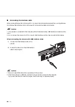
Страница 32: ...ll be used 2 Do not connect the scanner to 2 PCs one with USB Interface and the other one with SCSI interface When connecting the scanner with USB interface cable 1 Connect the USB interface cable to the scanner 2 Connect the other end of the USB interface cable to the computer NOTICE 1 Be sure to use USB cable which is provided with the scanner 2 When connecting to a USB hub use the first stage h...

Страница 33: ... If the ID of the scanner is the same as the other device change the ID via the operator panel or change the ID of the other device Setting the SCSI ID and the SCSI Terminator when using SCSI interface cable The default of the SCSI ID is 5 The SCSI ID is set by using the Setup mode of the operator panel 1 Turn the power Off by pressing the 0 side of the power switch 2 Turn the SCSI ID switch on th...

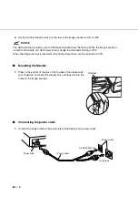
Страница 34: ...ting to OFF When the image scanner is located at the end the daisy chain set the terminator to ON Mounting the Stacker 1 Press in the bottom of the pins on both sides of the stacker with your fingertips and insert the stacker pins until they slot into the holes on the image scanner Connecting the power cable 1 Connect the power cable to the power inlet of the device and a power outlet Stacker Powe...

Страница 35: ...CHAPTER 3 1 3 HOW TO INSTALL THE DEVICE DRIVER This chapter describes how to install this software Procedure 3 2 ...

Страница 36: ... 3 2 For details on how to install the device driver refer to the attached installation guide and the device driver s user s guide in device driver s CD Procedure ...

Страница 37: ...ual for routine scanner maintenance Turning the Power On 4 2 Waking up the Scanner from the Low Power Mode 4 3 Manual Feed Mode Setting 4 4 Loading Documents on the ADF 4 5 Loading Documents on the Document bed 4 9 Loading Documents Larger than the Document bed 4 10 Reading a Page from a Thick Book 4 11 Clearing Paper Jams 4 12 ...

Страница 38: ... 4 2 This section describes how to turn the power On Press the I side of the power switch The power turns On and the green Power lamp at the operator panel lights Power OFF Power On Turning the Power On ...

Страница 39: ...ke up the Scanner simply press a button set the papers on the ADF or send a command to scan from the host computer NOTICE As an ENERGYSTAR partner PFU Limited declares that this scanner meets the ENERGYSTAR guidelines for energy efficiency Waking up the Scanner from the Low Power Mode ...

Страница 40: ...ner Ready is displayed on the LCD Screen M1 2 Press then the scanner displays Screen M2 Screen M2 3 Press then the scanner displays Screen M3 Screen M3 4 Press then the scanner displays Screen M4 Screen M4 5 Select Yes by pressing Then press 6 Press to return to the Scanner Ready screen Note that Manual Feed is shown on the LCD This means that the scanner is in Manual Feed mode Screen M1 R e a d y...

Страница 41: ...nts on the ADF paper chute For details see the next page NOTICE Be sure to change the position of the Shipping lock according to the Chapter2 Placing the Shipping lock page 2 3 procedure before operation ADF paper chute Guide Guide lever ADF lever Stacker ADF Bar Operating Position 10mm Document Loading Documents on the ADF ...

Страница 42: ...OTICE Reduce the batch size of the documents if Multi feed or mispick occurs NOTICE Note the following when preparing the paper Remove paper clips and staples Flatten the staple holes A preliminary document feed test may be necessary to avoid unexpected errors If document slip or jam in the ADF JAM error or Multi feed occurs frequently read the documents manually using the Document bed The followi...

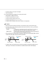
Страница 43: ...7 in size Documents other than paper such as fabric metal foil or transparencies When using the ADF the leading edge of all document sheets must be evenly aligned Make sure that curling at the leading edge is withtin the following toleranaces To avoid skewing do not feed documents of different widths during the same batch Adjust the stacker extension to the paper size Less than 3mm More than 30mm ...

Страница 44: ...des to the document width NOTICE Squeeze the guide lever to free the guides Do not load document stacks thicker than 8 mm Set the guides so that they touch the document sides After the read command is issued from the host system and the documents are read scanned documents are expelled into the stacker for removal Document Guide Guide leber Both sides max 8 mm 0 32 ...

Страница 45: ...pen the document cover Place the document face down and align the top left corner with the reference mark Slowly close the Document cover Issue the read command from the host system Document cover Document holding pad Document bed eference mark Loading Documents on the Document bed ...

Страница 46: ...y 90 degrees and lift up the cover in the direction of the arrow to remove it Place the document face down on the Document bed Issue the read command from the host system After the read operation remove the document re attach the Document cover and close it gently Document Document bed Loading Documents Larger than the Document bed ...

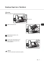
Страница 47: ... operation Open the Document cover Place the book face down on the Document bed Issue the read command from the host system Keep the cover open for the reading operation NOTICE Do not move the book during the read operation Thick book Reading a Page from a Thick Book ...

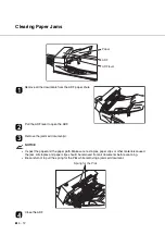
Страница 48: ...ct the paper and the paper path Make sure no staples paper clips or other materials caused the jam All staples and paper clips should be removed from all documents before scanning Be careful not to pull the spring for the Pick while removing a jammed document Close the ADF Paper ADF ADF lever Spring for the Pick Clearing Paper Jams ...

Страница 49: ...bes the document size and document quality required to use the ADF successfully Document Size 5 2 Document Quality 5 3 Maximum ADF Capacity 5 5 Areas not to be Perforated 5 6 Grounding Color Areas 5 7 Multi Feed Detection Conditions 5 8 Job Separation Sheet 5 9 ...

Страница 50: ... 5 2 The following figure shows document sizes that the scanner can read using the ADF Unit mm Scanner Maximum Minimum A B A B fi 4340C 216 8 5 in 356 14 in 53 2 1 in 74 2 9 in Document Size ...

Страница 51: ...ion must satisfy the specification described in the Grounding Color Area section Paper weight The paper weight should fall within the following ranges 52 to 127 g m2 13 9 to 34 lb 127g m2 34lb for A8 Precautions A preliminary document feed test may be necessary to avoid unexpected errors If document slip or jam in the ADF JAM error or Multi feed occurs frequently scan the documents manually using ...

Страница 52: ...ng Cleaning If mispicks occur frequently clean the Pad and Pick roller For details on cleaning method refer to the Cleaning and Maintenance manual Replacing parts The service life of the Pad and Pick roller may be shortened compared to the case of scanning wood containing paper documents When using the ADF the leading edge of all document sheets must be evenly aligned Make sure that curling at the...

Страница 53: ...aph shows the maximjum documents loading capacity of the ADF based on paper weight Paper weight conversion table Unit Conversion lb 13 9 17 20 24 27 9 34 41 8 g m2 52 64 75 90 104 127 157 80 79 63 61 A4 Letter or smaller 49 50 40 100 100 80 60 40 20 0 52 64 ADF Capacity g m2 81 104 127 Legal ADF chute loading number of pages Maximum ADF Capacity ...

Страница 54: ... errors If you must read data from such a paper use the Document bed 79 79 15 10 10 Unit mm Top of paper Read reference position Center of sensor arm Front side Feeding direction Center of paper Center of sensor arm Bottom of paper 35 Areas not to be Perforated ...

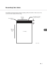
Страница 55: ...per grounding color white or drop out color If not turn the white level following Off when reading 3 Read reference position Grounding color white or drop out color area Unit mm Front Side Scanning direction sub Scanning direction main Grounding Color Areas ...

Страница 56: ...is not allowed 10 mm x 10 mm 4 No binding holes are allowed within 35 mm of the middle halfway point along the center of the paper 5 Printing duty 12 or less 6 The deviation of the amount of transparent light on the base color area should be less than 10 NOTICE Certain paper types or a certain condition of paper result in lower detection rates in terms of Multi feed detection 35 mm 10 mm No printi...

Страница 57: ...shows the typical format of the job separation sheet 2 Paper conditions Paper width must be A4 or larger 210 mm or larger in width 15 15 Feeding direction Top of paper Bottom of paper Center of paper Unit mm Job Separation Sheet ...

Страница 58: ... 5 10 ...

Страница 59: ... the components of the scanner part names and LED indicators After unpacking the scanner confirm that all components have been received by checking them against the list in the first section Counter Display 6 2 Operation status 6 3 Temporary error 6 4 Alarm 6 5 ...

Страница 60: ...on is pressed for at least 1 sec ond This counter increments each time a document is scanned It is not initialized until the power is turned off The counter can be used for example for checking the number of sheets that have been scanned in one day Abrasion counter The abrasion counter counts the accumulated number of scanned sheets This counter increments every 10 sheets It is useful to check the...

Страница 61: ...the Start button to be pressed Cleaning request When the ADF glass cleaning is necessary the scanner displays the following on the LCD When the Pick roller cleaning is necessary the scanner displays the following on the upper line When the ADF glass and the Pick roller cleaning are necessary the scanner displays the following Clean the Pick roller or the ADF glass in accordance with the manual Cle...

Страница 62: ... ADF completely Multi feed error This message is displayed when the ADF detects the Multi feed error Check the document and re scan the document No Ink Cartridge This message is displayed when the print cartridge is not put in fi 434PR Imprinter Please place the cartridge Print Error This message is displayed when the print position mark of fi 434PR Imprinter is set to the area which is out of the...

Страница 63: ...he ADF is less than 100 the message above and the message below are displayed alternately Remove the bracket Shipping Lock that holds the carrier in place Motor fuse alarm Lamp fuse alarm Image transfer alarm Memory alarm EEPROM alarm FAN alarm O p t i c a l A l a r m F r o n t S i d e O p t i c a l A l a r m B a c k S i d e M e c h a n i c a l A l a r F l a t b e d m L o c k C h e c k S h i p p i...

Страница 64: ...The Power indicator LED and Check lamp blink alternately Imprinter Alarm The Power Indicator LED and Check lamp blink alternately SCSI Controller Alarm USB Controller Alarm I P C B o a r d A l a r m a e r i r I p m n r m A l t o E e w d H r a a r r r r r A U B S l m a ...

Страница 65: ...CHAPTER 7 1 7 SETUP MODE This chapter describes the setup mode of the scanner Activating the Setup Mode 7 2 Contents of the Setup Mode 7 3 ...

Страница 66: ...nterface option displays Screen M2 Screen M2 3 Press then the scanner displays Screen M3 Screen M3 4 Press then the scanner displays Screen M4 Screen M4 5 Press Now the scanner is at Screen 1 page 7 5 in Setup mode NOTICE Any time you press you can return to the Scanner Ready screen R e a d y X X X X X 0 X X X X R e a d i n g M o d e M o d e S e l e c t 0 M M a n u a l F e e d M o d e S e l e c t ...

Страница 67: ... the scanner waits for the next document insertion after the last document was scanned Time 27 values from 1 to 1999 sec 30 sec 7 ADF front offset setting 2 Specifies the horizontal and vertical offset of the front side image when using the ADF Offset H 2 to 3 mm V 2 to 3 mm Offset H 0 mm V 0 mm 8 ADF back offset setting 2 Specifies the horizontal and vertical offset of the back side image when us...

Страница 68: ...15 mm Bottom 7 to 0 mm Left Right 0 mm Top 0 mm Bottom 0 mm 16 FB Edge Erasing Adjusts the edge areas to be erased from the image scanned by the flat bed FB Left Right 0 to 15 mm Top 0 to 15 mm Bottom 0 mm Left Right 0 mm Top 0 mm Bottom 0 mm 17 Select read color Selects the color to be read in unicolor reading R G B W G 18 Gray mode Switches between quality priority scanning and speed priority sc...

Страница 69: ...computer is valid the location of the blinking does not move when either button is pressed 1 No is blinking Paper thickness is not checked 2 Yes and 1 are blinking Paper thickness is checked However a detected Multi feed error is displayed on the screen only processing is continued 3 Yes and 2 Stop are blinking Paper thickness is checked When the Multi feed error is detected the scan processing is...

Страница 70: ...length is not checked 2 Yes and 1 are blinking Paper length is checked However a detected Multi feed error is displayed only on the screen processing is continued 3 Yes and 2 Stop are blinking Paper length is checked When the Multi feed error is detected the scan processing is stopped The error is then reported to the host If you want to disable the Multi feed select No then press Press to return ...

Страница 71: ...mage with good contrast Preset 3 OCR Smoothing Preset 4 Image Smoothing Preset 5 Dither Preset 9 Pre printed paper color Carbonless paper Carbonless paper The following built in IPC pre settings can be selected even though IPC 4D is not installed Sharpen Darken Character Copy Quality 3 At Screen 5 select Yes or No Note that when you select Yes the IPC setting from the Host computer is ignored If y...

Страница 72: ... to procedure 3 3 At Screen 7 or Screen 8 If you want to reset the abrasion counter select Reset through or button and press Go to procedure 4 If you do not want to reset the abrasion counter select No and press Finally press to return Screen 7 Screen 8 4 At Screen 9 If you want to reset the abrasion counter select Yes and press If you do not want to reset it select No and press Press to return Sc...

Страница 73: ...t set it as follows 1 Press Next or Previous and let the scanner display Screen 10 Screen 10 2 At Screen 10 press to increase the Pick start time or press to decrease the Pick start time Then press to activate the setting Finally press to return 1 0 S e c 0 5 P i c k s t a r t ...

Страница 74: ... 3 Press to return 7 ADF Front Offset Setting 8 ADF Back Offset Setting 9 Document bed Offset Setting 1 Press Next or Previous and let the scanner display the following For an ADF front offset setting Screen 12 For an ADF back offset setting Screen 13 For a Document bed offset setting Screen 14 3 0 S e c 0 6 T i m e o u t C h a n g e N o Y e 0 7 A D F F O f f s e t s C h a n g e N o Y e 0 8 A D F ...

Страница 75: ...set setting Screen 18 4 At Screen 16 Screen 17 or Screen 18 press to increase the offset or press to decrease offset The increment or decrement is 0 5 mm Then press to activate the setting The scanner displays Screen 19 Screen 20 or Screen 21 For an ADF front offset setting Screen 19 For an ADF back offset setting Screen 20 For a Document bed offset setting Screen 21 d e f a u l t N o Y e 0 X 1 R ...

Страница 76: ...ious if an IPC4D IMAGE PROCESSING CIRCUIT BOARD is installed Screen 22 will appear Screen 22 if an IPC4D IMAGE PROCESSING CIRCUIT BOARD is not installed Screen 23 will appear Screen 23 if a fi 434PR IMPRINTER only is installed Screen 24 will appear Screen 24 if fi 434PR IMPRINTER and IPC4D IMAGE PROCESSING CIRCUIT BOARD are installed Screen 25 will appear Screen 25 if a fi 475CMP3 JPEG COMPRESSION...

Страница 77: ...1 Press Next or Previous and let the scanner display Screen 30 Screen 30 2 At Screen 30 press or to select the time duration A minimum of 5 min to the maximum of 60 minutes can be selected Then press to activate the setting NOTICE The default time recommended by the ENERGYSTAR program is 15 minutes The default for the fi 4340C scanner is 15 minutes as recommended 3 Press to return N O O K O K 1 0 ...

Страница 78: ...activating the board in the third party slot Screen 31 and 31 2 can be used to forcibly change the selected interface The selected interface is then forcibly changed 3 The SCSI interface USB interface and the board installed in the third party slot cannot be used at the same time 4 The default is Auto 3 Press to return 13 Display the TPS Board ID Number 1 Press Next or Previous and let the scanner...

Страница 79: ...uilt in functions are enabled By setting On using the Operator Panel the IPC 4D image processing overrides the built in functions The IPC 4D IMGGE PROCESSING CIRCUIT BOARD support of those functions is intended for compatibility with the IPC 3 3D except for image quality The matrix size used in the IPC 4D IMAGE PROCESSING CIRCUIT BOARD is larger than the one in the fi 4340C The fi 4340C Built in D...

Страница 80: ...t upward from the bottom edge of the image With Down the area is set downward from the bottom edge of the image The value changes in 1 mm units Then press to activate the setting The scanner displays Screen 38 Screen 38 6 At Screen 38 press or to change the left setting The value changes in 1 mm units Then press to activate the setting The scanner displays Screen 39 Screen 39 7 At Screen 39 press ...

Страница 81: ...scanner displays Screen 43 Screen 43 5 At Screen 43 press or to change the bottom setting With Up the area is set upward from the bottom edge of the image With Down the area is set downward from the bottom edge of the image The value changes in 1 mm units Then press to activate the setting The scanner displays Screen 44 Screen 44 6 At Screen 44 press or to change the left setting The value changes...

Страница 82: ...n 47 on the LCD Screen 47 2 In Screen 47 press or to select Normal Fast Normal refers to quality priority mode When Normal is selected scanning is performed at a quality higher than that of the Fast mode Fast refers to the regular mode When Fast is selected scanning is performed at the machine defaults for image quality and speed The lower display of Screen 47 is switched as follows 1 Normal Fast ...

Страница 83: ...inter cannot print any more replace the print cartridge and reset the Ink remain counter as follows You must reset the ink remain counter even if you replace the print cartridge before its service life 1 Press Next or Previous and let the scanner display Screen 48 First No blinks Screen 48 2 press then Reser blinks Screen 49 Screen 49 3 Press The reset execution screen appears First No blinks Scre...

Страница 84: ... top margin of 7mm 1 Press Next or Previous and let the scanner display Screen 54 Screen 54 2 At Screen 54 press or to select On then Press if you want to activate the setting function The scanner displays Screen 55 indicating that the setting function is activated Screen 55 NOTICE When the setting function is disabled the Screen 56 Screen 56 3 At Screen 55 select the number of digits press or to ...

Страница 85: ...hopper empty Press or to select On if you want to initialize than press The scanner displays Screen 59 Screen 59 6 At Screen 59 specify whether the number is reset at once Press or to select yes if you want to reset at once than press The scanner terminates the setup mode NOTICE The command from the host computer overrides the specification of the operator panel When the host computer issues a com...

Страница 86: ... 7 22 ...

Страница 87: ...CHAPTER 8 1 8 TROUBLESHOOTING This chapter describes some potential problems and solutions that may occur when using this scanner Troubleshooting 8 2 ...

Страница 88: ...ing of Cleaning Maintenance Scan image is distorted or unclear Refer to Chapter 4 Troubleshooting of Cleaning Maintenance Scan image is striped Refer to Chapter 4 Troubleshooting of Cleaning Maintenance Check LED turns on Refer to Chapter 4 Troubleshooting of Cleaning Maintenance Clean pick roller LCD message Refer to Chapter 4 Troubleshooting of Cleaning Maintenance Clean ADF glass LCD message Re...

Страница 89: ...ES AND OPTIONS This chapter describes the consumables and options Consumables 9 2 Options 9 3 VIDEO INTERFACE BOARD 9 4 IPC 4D IMAGE PROCESSING CIRCUIT BOARD 9 9 fi 434PR IMPRINTER 9 10 fi 475CMP3 JPEG COMPRESSION BOARD 9 11 ...

Страница 90: ...ommended the scanner may not function properly The abrasion counter can be used to check the total number of documents scanned since the last replacement s NOTICE Refer to the Cleaning and Maintenance guide for replacing the consumables CAUTION Certain paper types or conditions might reduce the life of consumables Name Specification Remarks Pad ASSY PA03277 0002 Up to 100 000 sheets or one year Pi...

Страница 91: ...ct your sales agent or PFU Limited and Fujitsu Group Offices for more information Product name P N VIDEO INTERFACE BOARD CA02956 2391 IPC 4D IMAGE PROCESSING CIRCUIT BOARD CA02919 0521 fi 434PR IMPRINTER PA03237 D103 fi 475CMP3 JPEG COMPRESSION BOARD CA02956 2398 Options ...

Страница 92: ... along the rails of the third party slot Make sure that the connector is connected securely Secure the board with two screws CAUTION Protective measures are required to prevent damage from static electricity NOTICE When the scanner power is turned On again the scanner automatically recognizes the video interface board Plate Screws VIDEO INTERFACE BOARD VIDEO INTERFACE BOARD ...

Страница 93: ...d and changes the display Whenever you press the scanner returns to screen M1 1 Turn the power On and verify that Scanner Ready is displayed on the LCD Screen M1 2 Press then the scanner displays Screen M2 Screen M2 3 Press then the scanner displays Screen 1 Screen 1 4 Select ADF or FB by pressing or then press The scanner displays Screen 2 Screen 2 5 Select Simplex or Duplex by pressing or Then p...

Страница 94: ...t Front Density by pressing or As the cursor moves to the right may appear Then press The scanner displays Screen 7 Screen 7 Density display This parameter appears only when IPC 4D IMAGE PROCESSING CIRCUIT BOARD is installed Without IPC 4D option With IPC 4D option Description AT1 AT2 Very dark Dark Dynamic Threshold DTC mode Simplified Dynamic Threshold IPC mode Normal Light Very light A 4 A 3 L ...

Страница 95: ...Select Back Halftone when Duplex was specified by pressing or The parameters are the same as in step 11 Press to confirm The scanner displays Screen 10 Screen 10 Parameter Description No Halftone is Off Therefore binary reading is specified H1 Halftone with dither is specified H2 Halftone with error diffusion is specified L1 Automatic separation with dither is specified L2 Automatic separation wit...

Страница 96: ...ect the parameter by pressing or and finally press If all parameters are acceptable press to return to the Scanner Ready screen Parameter Description L Line White level following is ON Top 3mm part of the document must be left blank grounding color is drop out color Use this specification for reading line arts or texts P Photo White level following is Off Use this specification for reading photogr...

Страница 97: ...omatically optimize binary threshold level to separate text from back ground for high contrast output IPC 2 like Dynamic Threshold Optimizes the binary threshold level to separate text from background allowing light text to be captured while maintaining sharpness Noise Removal Dot removal size settable from 2x2 to 5x5 Optical noise speckles etc is automatically detected and removed from the output...

Страница 98: ...lphabet Letters A to Z a to z Numeric Characters 0 1 to 9 Symbols _ Maximum Number of Characters Printed 40 Character Size Height 2 91 mm to width 2 82 mm Character Pitch About 3 53 mm Printing Area The printable area of the backside of document is as follows T Length of document D 140 5mm for 40 columns C 70 0mm T C D 7mm Consumable Print Cartridge CA00050 0262 Center of Document D C T Backside C...

Страница 99: ...1 JPEG standard baseline process Format gray and multi color images JPEG Scan range duplex A3 600 dpi compression scans possible Compressed Process ing Real time duplex compression processing JPEG compression ratio Built in quantum table providing a 7 grade selection ranging from small compression rate prioritizing image quality to high compression rate pri oritizing size Other functions Quantum t...

Страница 100: ...i 475CMP3 JPEG COMPRESSION BOARD fully into the option slot along it s internal rails and fasten with the two screws provided CAUTION Protective measures are required to prevent damage from static electricity fi 475CMP3 ...

Страница 101: ...10 1 10 SCANNER SPECIFICATIONS This chapter describes the basic product specifications installation specifications and dimensions Basic Product Specification 10 2 Installation Specification 10 3 Dimensions 10 4 ...

Страница 102: ... Front Back 3 Light source White Xenon discharge tube x 2 Front Back 4 Document Size Minimum A8 Portrait 127g m2 Maximum A4 Letter Legal US Ledger 5 Paper Weight 52 g m2 14 lb to 127 g m2 34 lb Note 1 6 Scanning Speed Note 2 Mono chrome 40 pages min simplex 80 sides min duplex 200 dpi Note 3 Color 34 pages min simplex 48 sides min duplex 150 dpi 7 ADF Capacity 100 sheets A4 64 g m2 20 lb Note 3 8 ...

Страница 103: ...er to Chapter6 Counter Display page 6 2 NOTICE Refer to the Cleaning and Maintenance guide for replacing the consumables Item Specification Dimensions mm Without ADF paper chute and Stacker Depth Width Height 423 16 6 in 556 21 9 in 220 8 7 in Weight kg 15 48 4 lb Input power Voltage 100 to 120 VAC 10 or 220 to 240 VAC 10 Phases Single phase Frequency 50 60 3 Hz Power consumption 125 VA or less Am...

Страница 104: ... 10 4 423 16 6 360 14 2 556 21 9 220 8 7 275 10 8 unit mm Dimensions ...

Страница 105: ...and another device such as a scanner Automatic separation An image processing method in which the scanner automatically detects difference between text and photos and chooses the threshold accordingly Automatic separation allows the scanner to switch between line mode and half tone mode in one pass Automatic start mode manual start mode In this mode the reading operation is activated only by issui...

Страница 106: ...s maintains high grayscale levels and resolution during reading while suppressing more patterns by dotted halftone images such as newspaper photographs FB In this manual FB means flat bed Filtering A correction method that improves the read quality of handwritten documents The read quality of images written in pencil or ball pointed pen depends on the reflective light characteristics of the specif...

Страница 107: ...e processing option of this scanner IRAS Initialization of the hardware Landscape orientation A document is transported and read with the long side vertical to the moving direction Letter size A standard paper size used in the U S A and other countries Paper size is 8 1 2 x 11 inches Linedrawing mode Selecting linedrawing mode makes threshold and contrast settings effective but prevents brightness...

Страница 108: ...nsity making it suitable in scanning images such as photographs having gradations Photo mode photograph mode A photograph is read properly in this mode Pick start time The period from the manual insertion of the document until picking starts after the document passes the hopper empty sensor Portrait orientation A document is transported and read with the long side parallel to the moving direction ...

Страница 109: ...tor Devices with a SCSI interface can be daisy chained A resistor that includes terminal circuits needs to be placed at both ends of a cable when devices are daisy chained If a device such as a scanner is the last device in a chain leaving an interface connector unused a Terminator theerfore must be attached to provide those terminal circits Third Party Interface Optional board provided by Fujitsu...

Страница 110: ... GL 6 ...

Страница 111: ...ze 5 2 type 4 6 5 3 Duplex reading mode 9 5 E Enter button 1 7 Exit button 1 7 F FB erasing edges 7 17 Feeding direction 5 2 G Grayscale mode setting 7 18 H Halfone processing 9 7 Heat capacity 10 3 Hopper empty 6 4 I Image processing circuit 7 4 7 15 Input power 10 3 Installation specifications 10 3 Interface connectors 1 4 Interface select 7 14 IPC mode select 7 4 7 15 preset mode setting 7 3 7 ...

Страница 112: ...Counter 7 19 Inprinter 7 20 IPC preset mode 7 7 IPC Status Display 7 12 low power mode 7 13 Multi feed detection paper length 7 6 paper thickness 7 5 Numbering Print Function 7 20 Offset 7 10 pick start time 7 9 SCSI terminator 7 13 time out limit 7 10 Unicolor Reading 7 18 Setup mode 7 2 7 3 Simplex 9 5 Size 9 6 Specifications 10 2 10 3 Start button 1 6 1 7 Stop button 1 6 1 7 T Temporary error 6...

Страница 113: ... IN 3 Send To button 1 7 Start button 1 7 Stop button 1 7 ...

Страница 114: ... of this manual in whole or in part and copying of the scanner application is forbidden under the copyright law The contents of this manual are subject to change without notice PFU LIMITED assumes no liability for incidental or consequential damages arising from the use of this manual and any claims by a third party ...

Отзывы: