background image

 2-14

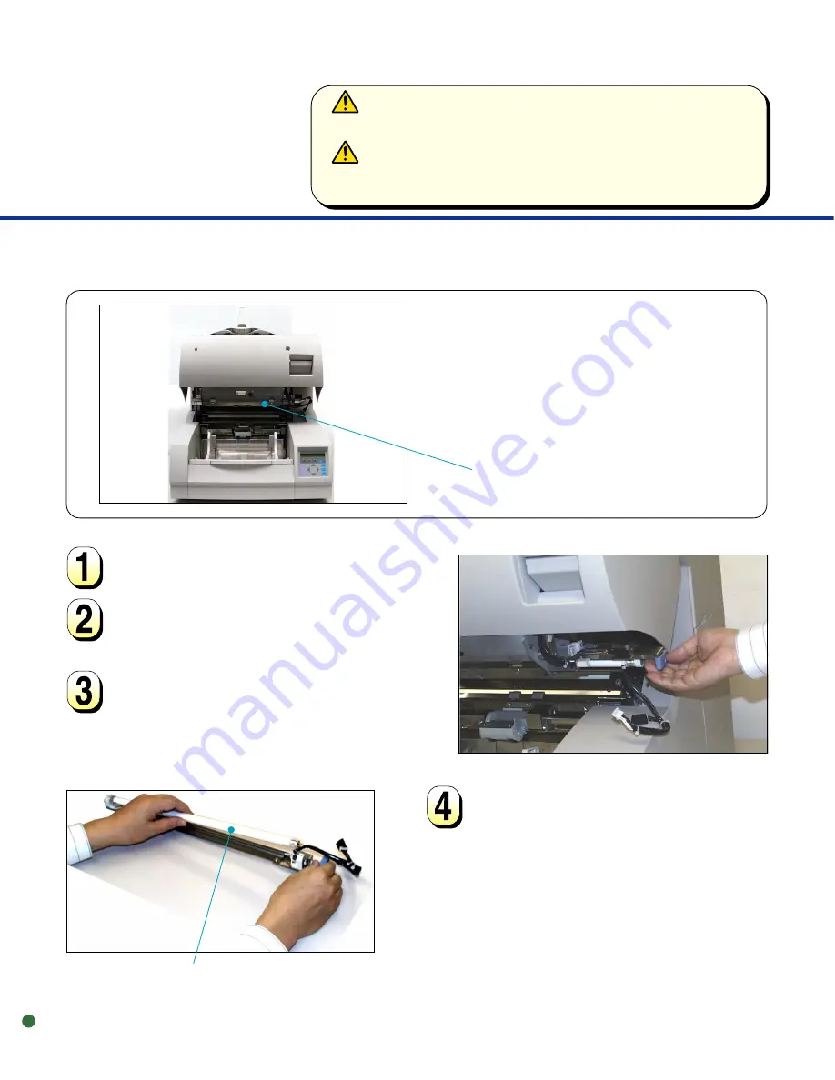
Remove the connector of the
front-side lamp unit.

Rotate the lamp a half turn so that
the two terminals on each end
align with the slot on the lamp
socket and remove the lamp from
the front-side lamp unit.

Open the upper transport unit.

Front-Side Lamp

Front-side Lamp unit (inside)

Pull out the front-side lamp unit
toward the right.

Lamp


WARNING

Wait at least 3 minutes after turning off the power before cleaning.


ACHTUNG

Warten Sie nach dem Reinigen mindestens 3 Minuten bevor Sie den
Scanner wieder anschalten.

Содержание 4099D - M VRS

Страница 1: ...Reference Guide M4099D Image Scanner ...

Страница 2: ...ation of this equipment in a residential area is likely to cause harmful interference in which case the user will be required to correct the interference at his own expense This digital apparatus does not exceed the Class A limit for radio noise emissions fromdigitalapparatussetoutintheRadiointerferenceRegulationsoftheCanadian Department of Communications Lepésentappareilnumériquen émentpasdebruit...

Страница 3: ... FUJITSU HONG KONG LTD 10 F Lincoln House Taikoo Place 979 King s Road Island East Hong Kong Phone 852 2827 5780 Fax 852 2827 4724 HOME PAGE http www fujitsu com hk FUJITSU KOREA LTD 6th Fl Korea Financial center building Yoido Dong 23 6 Young DungPo gu Seoul Republic of Korea Phone 82 2 3787 6000 FaX 82 2 3787 6029 HOME PAGE http www fujitsu co kr FUJITSU COMPUTER SINGAPORE PTE LTD 20 Science Par...

Страница 4: ...ether such errors are omissions or statements resulting from negligence accidents or any other cause FUJITSU further assumes no liability arising from the application or use of any product or system described herein nor any liability for incidental or consequential damages arising from the use of this manual FUJITSU disclaims all warranties regarding the information contained herein whether expres...

Страница 5: ...replacement adjustment and troubleshooting Refer to Operator s Guide for the basic information about the M4099D The M4099D is very fast and highly functional image scanner developed for volume filing using charge coupled device CCD image sensors Thisscannerfeaturesduplexscanningandhighqualityimage processing with an automatic document feeder ADF ...

Страница 6: ...onal injury may result if you do not follow procedure correctly CAUTION CAUTION indicates that damage to the scanner may result if you do not follow a procedure correctly The following symbols are used in this manual Used for general WARNING and CAUTION Indicates that care must be taken to avoid injury to hands or fingers ...

Страница 7: ...iv ...

Страница 8: ...llers 2 3 Transport Path Discharge Brush and Glass Surface 2 6 Sensors 2 12 Front Side Lamp 2 14 Back Side Lamp 2 16 CHAPTER 3 REPLACEMENT OF PARTS 3 1 Front Side Lamp 3 2 Back Side Lamp 3 4 Pick Roller Unit 3 6 Brake Roller 3 8 Pad 3 11 CHAPTER 4 ADJUSTMENT 4 1 Improving Paper Separation 4 2 CHAPTER 5 TROUBLESHOOTING 5 1 Paper Jam 5 2 Initial Checks 5 5 Messages and Actions 5 13 Problem Checklist...

Страница 9: ...TER 1 OPERATING INSTRUCTIONS CHAPTER 2 CLEANING CHAPTER 3 REPLACEMENT OF PARTS CHAPTER 4 ADJUSTMENT CHAPTER 5 TROUBLESHOOTING TROUBLESHOOTING ADJUSTMENT REPLACEMENT OF PARTS CLEANING OPERATING INSTRUCTIONS ...

Страница 10: ...ibeshowtoloaddocuments howtoinsertdocuments manually and how to open close the upper transport unit Units and Assemblies Loading Documents Inserting Documents Manually Upper Transport Unit OPERATING INSTRUCTIONS CHAPTER 1 ...

Страница 11: ... 1 Operator panel 2 Power switch 4 Hopper guide 5 Hopper extension 6 Automatic document feeder ADF 8 Pick roller unit 9 Guide plate 10 Pad 11 Brake roller 12 Upper transport unit 13 Side cover 14 Lever 16 Stacker guide 17 Stacker extension 19 Check stopper 18 Stop lever 15 Stacker 7 ADF release lever 23 Interface connectors 21 Power inlet 20 Main line switch 22 Interface connectors ...

Страница 12: ...page from document stack 11 Brake roller Separates top page from document stack 12 Upper transport unit Opens for easy access 13 Side cover Opens to access back side lamp 14 Lever Used to open the upper transport unit 15 Stacker Document exit tray 16 Stacker guide Helps guide documents into stacker 17 Stacker extension For use with long documents 18 Stop lever Used to keep documents in the stacker...

Страница 13: ...1 4 Assemblies Lower sheet guide assembly Brake roller Pick roller unit Pad Guide plate Lamp Lamp Back side lamp unit Front side lamp unit ...

Страница 14: ...es to the document width And load documents face up Load the document for reading Stacker Lever Hopper guide Hopper table Extension 15 to 20 mm Fan the sheets before setting the document on the hopper table NOTE Squeeze the lock lever to free the Hopper guides Remove paper clips and staples Flatten staple holes with your finger Load documents face up Stack must not exceed line mark Use the extensi...

Страница 15: ...4 or LT Raise the stopper for small sizes of paper and adjust the stacker guides to the width of the paper and push down the stacker table to lock it Stopper adjustment Stopper Document about 20 mm Stop lever Stacker table Check stopper Stacker Scanned documents are stacked in the stacker for removal Stacker guide Stacker guide ...

Страница 16: ...de set the documents as follows NOTE For information on setting Manual feed timeout see the Operating Instructions in the Operator s Guide Insert the documents until the leading edge touches the guide plate of the hopper table Adjust the guides to the document width Place documents face up at the center of the hopper table CAUTION Be careful not to catch your fingers or something in the mechanism ...

Страница 17: ...ocked position before reaching inside the scanner Lift the upper transport unit to release the lock Lever NOTE Press the upper transport unit with both hands to secure the lock Upper transport unit WARNING Before lowering down the unit make sure that the area between the main machine and the upper transport unit is clear of all objects and fingers ACHTUNG Bevor Sie die obere Einheit absenken überz...

Страница 18: ... describes the tools and methods required to keep your scanner clean Cleaning Tools and Roller Position Rollers Transport Path Discharge Brush and Glass Surface Sensors Front Side Lamp Back side Lamp CLEANING 2 CHAPTER ...

Страница 19: ...per with almost all printed area Paper with special coating such as carbonless paper Tools Type No Frequencies Remarks Cleaning sheet CA99501 0016 Every 50 000 sheets 20 sheets 1 pack Cleaner F2 CA99501 0014 Front side and 1 bottle back side lamp Every 100 000 sheets Roller Every 100 000 sheets Isopropyl alcohol CA99501 0013 Discharge brush 1 bottle or Cleaner F1 Every 100 000 sheets Others Every ...

Страница 20: ... table guides to B4 width Then set the offline feed test mode as follows While pressing MENU turn on the power the LCD displays Please wait then the MODE SELECT screen appears with SETUP blinking Press Õ twice TEST blinks Press ENTER three times The OFFLINE FEED TEST screen appears with START blinking Hopper guide left Front Cleaning sheet Cleaning sheet Protective paper Remove the protective pape...

Страница 21: ...gning with the hopper guide right Then press ENTER the cleaning sheet is fed When Hopper empty is displayed press CANCEL Remove the protective paper from a new cleaning sheet and place it with the adhesive side face down Then repeat steps through After cleaning is complete turn the power off Cleaning sheet Front Hopper guide right ...

Страница 22: ... WARNING Do not use cleaner F2 on rubber rollers Metal rollers hidden lower transport unit side Rollers hidden upper transport unit side Brake roller hidden Pick roller unit Metal roller Cleaning the Rollers with Dry Cloth Isopropyl Alcohol or Cleaner F1 Cleaning the Metal Rollers with Cleaner F2 Rollers Pick roller unit Brake roller hidden Cloth WARNING Wait at least 3 minutes after turning off t...

Страница 23: ...port unit Transport Path Discharge Brush and Glass Surface NOTE Use a vacuum cleaner to remove paper dust from the transport path Cleaning the Discharge Brush Open the upper transport unit Release the ADF release lever and rest the ADF sheet guide assembly on the ADF release lever While pulling the ADF release lever toward you hold up the ADF sheet guide assembly CAUTION Never close the upper tran...

Страница 24: ...ove it toward the upper right Turn the lever of the brake roller upward and pull out the brake roller upward Holding the top of the guide plate press the guide plate down and lift it toward you to remove it Guide plate Hopper guide Brake roller ...

Страница 25: ...brake roller until it locks Put the guide plate in position NOTE Confirm that the guide plate is installed correctly If it is miss connected it will cause paper jams and noise by touching the hopper table Discharge brush for brake roller Discharge brush for pick roller unit ...

Страница 26: ... the ADF sheet guide assembly up pull the ADF release lever toward you then gently lower the ADF sheet guide assembly Release the ADF release lever to lock the ADF sheet guide assembly into position Close the upper transport unit CAUTION Hold the ADF sheet guide assembly during this process to avoid damage to the sensors ADF release levers ...

Страница 27: ...necessary Cleaning the Glass Surface Upper sheet guide assembly Open the upper transport unit Close the upper transport unit Close the upper sheet guide assembly and tighten the two knurled screws Upper sheet guide assembly Knurled screws WARNING Wait at least 3 minutes after turning off the power before cleaning ACHTUNG Warten Sie nach dem Reinigen mindestens 3 Minuten bevor Sie den Scanner wiede...

Страница 28: ...urface Lower sheet guide assembly Open the upper transport unit Close the upper transport unit Align the lower sheet guide assembly in the guide rails and push it back into place Lower sheet guide assembly Glass Tab WARNING Wait at least 3 minutes after turning off the power before cleaning ACHTUNG Warten Sie nach dem Reinigen mindestens 3 Minuten bevor Sie den Scanner wieder anschalten ...

Страница 29: ...e the upper transport unit Close the ADF sheet guide assembly Open the upper transport unit Sensors ADF sheet guide assembly SF2 sensor inside Document width detection sensors inside Document width detection sensors lower Document width detection sensors upper ADF release levers WARNING Wait at least 3 minutes after turning off the power before cleaning ACHTUNG Warten Sie nach dem Reinigen mindest...

Страница 30: ...ce with a dry cloth or a cotton swab or moistened with isopropyl alcohol as necessary Wipe the SF2 sensors in the transport path with a dry cloth or moistened with isopropyl alcohol as necessary SF3 Sensors Open the upper transport unit Close the upper transport unit Open the upper transport unit Close the upper transport unit SF3 sensors located at upper and lower sides SF2 sensors located at upp...

Страница 31: ...ket and remove the lamp from the front side lamp unit Open the upper transport unit Front Side Lamp Front side Lamp unit inside Pull out the front side lamp unit toward the right Lamp WARNING Wait at least 3 minutes after turning off the power before cleaning ACHTUNG Warten Sie nach dem Reinigen mindestens 3 Minuten bevor Sie den Scanner wieder anschalten ...

Страница 32: ...nit Insert the terminals of the lamp into the socket and rotate the lamp Be sure that the clear portion is positioned as shown left otherwise black stripes may appear in the scanned image Put the front side lamp unit into the upper transport unit using the two guide grooves and rails until it locks Clear portion Guide grooves one hidden Rail Front side lamp ...

Страница 33: ... lamp socket and remove the lamp from the back side lamp unit Pull and open the side cover Pull out the back side lamp unit toward the right Back side lamp unit inside Side cover Lamp Rail WARNING Wait at least 3 minutes after turning off the power before cleaning ACHTUNG Warten Sie nach dem Reinigen mindestens 3 Minuten bevor Sie den Scanner wieder anschalten ...

Страница 34: ...he lamp Be sure that the clear portion is positioned as shown left otherwise black stripes may appear in the scanned image Re install the lamp unit using the two guide grooves and rails Close the side cover securely otherwise the cover open error may occur Rail Guide grooves one hidden Clear portion Connect the connector of the back side lamp unit Back side lamp ...

Страница 35: ...2 18 ...

Страница 36: ...This chapter describes how to replace parts of the scanner Front Side Lamp Back Side Lamp Pick Roller Unit Brake Roller Pad REPLACEMENT OF PARTS 3 3 1 CHAPTER ...

Страница 37: ... the connector of the front side lamp unit Front side lamp unit inside Pull out the front side lamp unit toward the right Lamp WARNING Never replace the lamp without turning off the power Wait at least 3 minutes after turning off the power before touching the lamp ACHTUNG Wechseln Sie niemals die Lampe ohne den Scanner auszuschalten Warten Sie mindestens 3 Minuten nach Ausschalten bevor Sie die La...

Страница 38: ... the clear portion is positioned as shown right otherwise black stripes may appear in the scanned image Connect the lamp connector Close the upper transport unit Clear portion Put the front side lamp unit into the upper transport unit using the two guide grooves and rails until it locks Guide grooves one hidden Rail Front side lamp ...

Страница 39: ...d the right Back side lamp unit inside Side cover WARNING Never replace the lamp without turning off the power Wait at least 3 minutes after turning off the power before touching the lamp ACHTUNG Wechseln Sie niemals die Lampe ohne den Scanner auszuschalten Warten Sie mindestens 3 Minuten nach Ausschalten bevor Sie die Lampe anfassen ...

Страница 40: ...ooves and rails Install a new lamp in the back side lamp unit Insert the terminals of the lamp into the socket and rotate the lamp Be sure that the clear portion is positioned as shown left otherwise black stripes may appear in the scanned image Close the side cover securely otherwise the cover open error may occur Lamp Rail Rail Guide grooves one hidden Clear portion Connect the connector of the ...

Страница 41: ...release lever and rest the ADF sheet guide assembly on the ADF release lever While pulling the ADF release lever toward you hold up the ADF sheet guide assembly Set consumable counter when replacing the pick roller unit See Appendix ADF sheet guide assembly ADF release levers Pick roller unit CAUTION Never close the upper transport unit in this condition Doing so will cause severe damage to the sc...

Страница 42: ...n its head Right Wrong While holding the ADF sheet guide assembly up pull the ADF release lever toward you then gently lower the ADF sheet guide assembly Release the ADF release lever to lock the ADF sheet guide assembly into position Close the upper transport unit CAUTION Hold the ADF sheet guide assembly during this process to avoid damage to the sensors ADF release levers ...

Страница 43: ...er See Appendix Brake Roller ADF sheet guide assembly ADF release levers Brake roller inside Open the upper transport unit Release the ADF release lever and rest the ADF sheet guide assembly on the ADF release lever While pulling the ADF release lever toward you hold up the ADF sheet guide assembly CAUTION Never close the upper transport unit in this condition otherwise some component parts will b...

Страница 44: ... press the guide plate down and lift it toward you to remove it Attach a new brake roller until it locks Put the guide plate in position Guide plate Hopper guide Brake roller NOTE Confirm that the guide plate is installed correctly If it is miss connected it will cause paper jams and noise by touching the hopper table ...

Страница 45: ...oward you then gently lower the ADF sheet guide assembly Release the ADF release lever to lock the ADF sheet guide assembly into position CAUTION Hold the ADF sheet guide assembly during this process to avoid damage to the sensors Close the upper transport unit ADF release levers ...

Страница 46: ... dem Austausch beginnen Open the upper transport unit Release the ADF release lever and rest the ADF sheet guide assembly on the ADF release lever While pulling the ADF release lever toward you hold up the ADF sheet guide assembly CAUTION Never close the upper transport unit in this condition Doing so will cause severe damage to the scanner ADF sheet guide assembly Pick roller unit Pad Guide plate...

Страница 47: ...e press the guide plate down and lift it toward you to remove it Press the rolled tab to remove the pad from the guide plate Attach a new pad to the guide plate Guide plate Hopper guide Rolled tab Pad Guide plate Guide plate Pad Rolled tab ...

Страница 48: ... release lever toward you then gently lower the ADF sheet guide assembly Release the ADF release lever to lock the ADF sheet guide assembly into position Close the upper transport unit CAUTION Hold the ADF sheet guide assembly during this process to avoid damage to the sensors ADF release levers ...

Страница 49: ...3 14 ...

Страница 50: ...This chapter describes the improving paper separation Improving Paper Separation ADJUSTMENT 4 4 1 CHAPTER ...

Страница 51: ...ke roller Setting Thick Medium Thick Normal Medium Thin Thin Select Picking Speed in setup mode and adjust the rotational speed of the pick roller Braking power Strong Less strong Medium factory default Less weak Weak Double feed frequently occurs Mis pick or SF2 frequently occurs Make the braking power stronger Make the braking power weaker Picking speed Fast factory default Slow Mis pick frequen...

Страница 52: ...This chapter describes the paper jam initial checks messages and actions and problem checklist Paper Jam Initial Checks Messages and Actions Problem Checklist Appendix TROUBLESHOOTING 5 5 1 CHAPTER ...

Страница 53: ...e the ADF release lever and rest the ADF sheet guide assembly on the ADF release lever While pulling the ADF release lever toward you hold up the ADF sheet guide assembly CAUTION Never close the upper transport unit in this condition Doing so will cause severe damage to the scanner ADF release levers ...

Страница 54: ...ver toward you then gently lower the ADF sheet guide assembly Release the ADF release lever to lock the ADF sheet guide assembly into position CAUTION Hold the ADF sheet guide assembly during this process to avoid damage to the sensors Close the upper transport unit Jammed paper ADF release levers ...

Страница 55: ... guide assembly Pull out the jammed paper to the stacker side Open the upper transport unit Close the upper transport unit Open the upper transport unit Close the upper transport unit Jam at Transport Path Jam at Ejection Jammed paper Stacker Jammed paper ...

Страница 56: ...a manufacturer s authorized service center Initial Checks Operator panel Is the main line switch on Is the power cable connected correctly Connect the power cable correctly Did you press the power switch on the operator panel Press the I side of the main line switch Press the power switch on the operator panel POWER Power cable Power main switch Power switch ...

Страница 57: ...faces Load the documents properly See p1 5 Connect the interface cable properly Or set the correct baud rate Read processing does not start Interface cable Turn the power off and on to check if read processing starts When read processing does not start contact a manufacturer s authorized service center CHECK Operator panel POWER Does the CHECK lamp blink Messages and Actions See p5 13 Operator pan...

Страница 58: ...re not read correctly Is Photo mode selected Clean the rollers transport path glass and lamps See Chapter 2 Re attach the lamp See p2 14 to 2 17 p3 2 to 3 5 Select the Photo mode White level following off through the scanner setting menu in the software Transport path Select a halftone or dithering mode from the host computer Is halftone or dithering processing selected NO YES Lamp ...

Страница 59: ...ansport path Transport path Characters and lines are not read correctly Is Line Art mode selected Clean the rollers transport path glass and lamps See Chapter 2 Contact a manufacturer s authorized service center Select Line Art mode from the host computer ...

Страница 60: ...O NO Is the lamp surface dirty Is the lamp burned out Is the linedrawing mode selected And does the text appear on the first 3 mm of the page Black stripes appear in the image of the display Clean the lamp surface See p2 14 to 2 17 Select photo mode Replace the lamp See p3 2 to 3 5 ...

Страница 61: ...Hopper empty Set the document Cover open Close the side cover Close the Endorser cover Mis pick Go to Symptom 7 Pick roller unit not set Set the pick roller unit Hopper overload Reduce document stack in hopper Turn the power off once and on again Contact a manufacturer s authorized service center Does the CHECK lamp still blink YES NO End CHECK CHECK Operator panel ...

Страница 62: ...r paper path dirty Smooth out the curled paper or reduce document stack in hopper See p1 5 Clean the pick rollers separation roller brake roller pad or paper path See Chapter 2 YES NO YES Is the roller worn out See Appendix Mount the pick roller unit and brake roller correctly See p3 6 to 3 10 Replace the roller Are the pick roller unit and brake roller in the correct position NO ...

Страница 63: ...5 12 Contact a manufacturer s authorized service center ...

Страница 64: ...turn the jammed or double feed document to the hopper and read it again Press the CANCEL button or issue the start command Load documents on the hopper and ENTER reading them Close the upper transport unit or the endorser cover Or the side cover Open the upper transport unit and remove the document on the transport path Close the unit Return the jammed document on the hopper and read it again Open...

Страница 65: ... authorized service center If turning the power on again does not recover the scanner contact a manufacturer s authorized service center Lamp Alarm Front Lamp Alarm Back Optical error Front Optical error Back Hopper over run Paper feed error Clear paper path to continue Hardware alarm EEPROM alarm Heater Alarm 1 Heater Alarm 2 Make sure that there is not anything on the hopper table or in the tran...

Страница 66: ... on the version label located at the bottom right of the rear of the equipment The version is checked with the double line This example is for A3 version Dateofpurchase Symptoms Persistent problem Serviced before when and how Transport error Error message if any Type of document What is your daily usage Date of last cleaning Dateoftheconsumable replacement Image error Interface controller model So...

Страница 67: ...tting the consumable counter Press MENU when the LCD displays Ready The MODE SELECT screen appears with SETUP blinking Press ENTER twice The Settings screen appears or Paper Length Check Press eleven times The Consumable Counter screen appears Press ENTER The value of the consumable counter is displayed in ten thousands of sheets Press or The value changes 001 to 256 Holding down or speeds up the ...

Страница 68: ...fe alarm which is displayed when the consumable counter reaches the prescribed value the LCD indicates an alarm that the consumable may be expired In this case press CANCEL to proceed the next operation usually you reset the counter after replacing the consumable The LCD indicates the following message Reset Consumable Counter Yes Enter No Cancel Yes Enter The scanner resets the consumable counter...

Страница 69: ......

Отзывы: