13
5. EXPLANATION TO THE END USER
(1) Refer to the Operation Manual, explain the operation of this range hood to end
users.
(2) The Installation Manual and Operation Manual should be given to the end user.
INSTALLATION (continued)
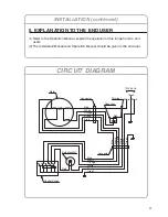
CIRCUIT DIAGRAM
Motor
Connector
Connector
Terminal
Capacitor
Red
Red
Red
White
White
Orange
Brown
Blue
White
Or
ange
Bro
wn
Blue
Green
Green
Black
Blac
k
White
Orange
Brown
Blue
Green
Black
120V 60Hz
Bulb:Max40W
Control Switch


