


MICREX-F Series SIO Driver
GP-Pro EX Device/PLC Connection Manual
3
1
System Configuration
The system configuration in the case when the External Device of Fuji Electric Co.,Ltd. and the Display are
connected is shown.
Connection Configuration
RS232C
•
1:1 Connection
Series
CPU
Link I/F
SIO Type
Setting Example
Cable
Diagram
File
Switch
MICREX-F
F80H
F120H
F250
RS232C interface
on FFU120B
RS232C
Setting
Example 1
(page 8)
Setting
Example 2
(page 11)
Cable
Diagram 1
(page 29)
RS485 interface
on FFU120B
RS422/485
(4wire)
Setting
Example 3
(page 13)
Setting
Example 4
(page 16)
Cable
Diagram 2
(page 32)
F30
*1
F50
*1
F60
F70
F70S
F80
F80H
F81
F120
F120H
F120S
F200
F250
*1
When you use F30 or F50 for T link connection, T link master adaptor (FTM050A) is necessary.
RS232C interface
on FFK120A-C10
RS232C
Setting
Example 1
(page 8)
Setting
Example 5
(page 18)
Cable
Diagram 1
(page 29)
RS485 interface
on FFK120A-C10
RS422/485
(4wire)
Setting
Example 3
(page 13)
Setting
Example 6
(page 20)
Cable
Diagram 2
(page 32)
FFK100A-C10
*2
*2
You cannot use FFK100A-C10 or NC1L-RS2 in 1:n configuration.
RS232C
---
Setting
Example 7
(page 22)
Cable
Diagram 3
(page 42)
F70
F70S
NC1L-RS2
*2 *3
*3
When you install 2 link units on the extension base unit created by T link function based on the basic base
unit of the External Device, you can connect the Display on either of 2 link units (simultaneous connection
on both 2 link units are not available). When you install 2 basic base units, simultaneous connection on both
2 link units are available.
RS232C
Setting
Example 1
(page 8)
Setting
Example 2
(page 11)
Cable
Diagram 4
(page 43)
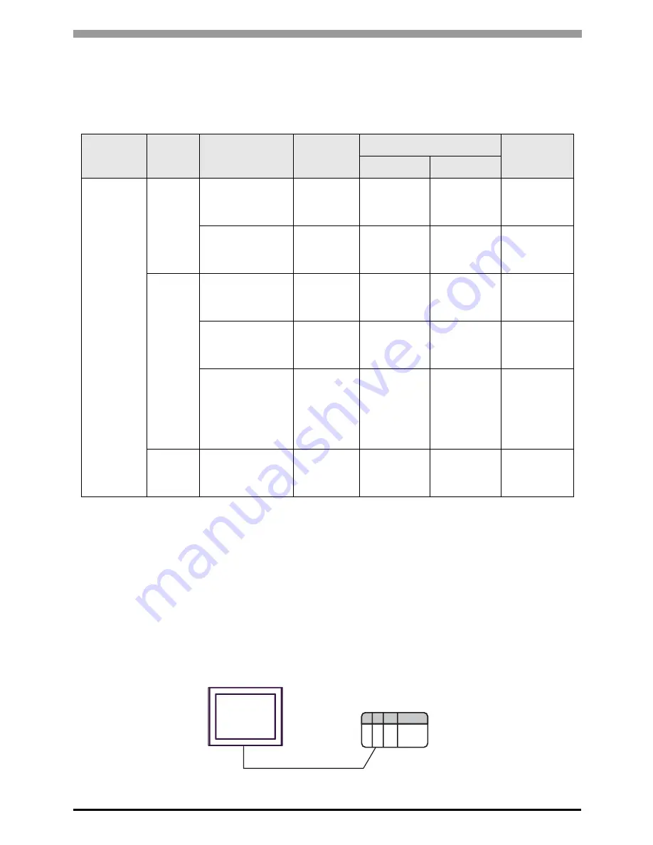
External Device
RS232C
Display
Operation mode:1


