LM2A Wall Mounted Solution
Page
13
of
20
Fuji Electric Europe GmbH
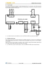
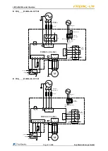
Note *1: All items inside this box are default or option elements of the Wall Mounted solution. Items located out
of this box are external and not included.
Note *2: Install a recommended molded case circuit breaker (MCCB) or residual-current-operated protective
device (RCD)/earth leakage circuit breaker (ELCB) (with over current protection function) in the primary
circuit of the inverter to protect wiring
Note *3: To bring the inverter into compliance with the European electrical safety standard IEC/EN 61800-5-1 or
compliance with Canadian and U.S. standards (CSA certification), be sure to insert the specified fuse
(see Instruction Manual) in the primary circuit of the inverter.
Note *4: In case of not installing the two MC between motor and inverter, please follow the procedure explained
in
“
AN-Lift2-0001 Use of FRENIC-Lift STO inputs in elevator applications
”
document.
Note *5: Use the metal plates placed on removable terminals to connect the shield by means of metal cable ties
for example.
Note *6: Braking resistor is optional.
Note *7: Connect an external power supply 230 VAC to terminals [1] and [2] of the common terminals for the
contactor coils.
Note *8: Jumper to connect/disconnect internal EMC filter. It is a metal plate placed on the EMC terminal.
Note *9: Removable terminals. For detailed information, refer to FRENIC-Lift LM2A series Instruction Manual,
section 2.2.4.
Note *10: Terminal configuration is set to SOURCE. Changing this configuration will make that the Wall Mounted
solution do not work properly.
Note *11: Wired to terminals (Y3A/C). It is mandatory to set the parameter E22 to value 123 (SCC function) for the
proper function of the Wall Mounted solution.
Note *12: Wired to the terminal (X4). It is mandatory to set the parameter E04 to value 115 (SCCF function) for the
proper function of the Wall Mounted solution.
2.4 Wiring and terminals
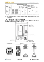
Follow the procedure below. In the following description, it is assumed that the Wall Mounted solution has already
been installed.
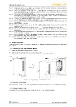
2.4.1 Removing the front cover of the Wall Mounted
[1]
Loosen up the screws of the Wall Mounted solution.
[2]
Hold the right and left ends of the top cover and remove it.
(It is possible to remove the ground connection from the cover to ease the procedure.)
Figure 2.2 Removing the Top Cover of the Wall Mounted Solution
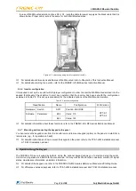
2.4.2 Mounting the front cover
After wiring, place, wire the ground cable if it was removed and screw the top cover of the Wall Mounted solution.
2.4.3 Recommended wire sizes
Terminals for the main circuits should have insulation, insulation tubes, or similar treatment.


