


Installation and commissioning
CAP-834
26
NOTICE!
Risk of material damage from
condensation!
Cooling air with moisture content can
cause condensation.
- Make sure that the cooling air is
cool, dry and free of dust.
1.
Provide the required rate of cooling air as per
the technical data for the screw compressor
(
Chapter 3 ‘Technical data’ on page 20
).
2.
Extract the exhaust air as per the technical data
for the screw compressor (
Chapter 3
‘Technical data’ on page 20
).
This prevents the installation room and the
screw compressor from heating up.
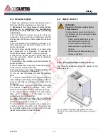
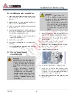
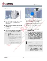
Forced ventilation and bleeding system
(optional)
The forced ventilation and bleeding
equipment must be dimensioned so
that the required supply and exhaust
air can be supplied and extracted
taking into account the existing residual
thrust from the cooling air fan. The
exhaust air can also be used for heat
reclamation.
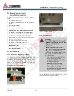
Fig. 23: Overview illustration of air duct connection
1.
For the nominal diameters of the duct connec-
tions and details about residual thrust refer to
the technical data (
Chapter 3 ‘Technical data’
on page 20
) and the installation diagrams in-
cluded in the scope of delivery.
2.
When connecting air ducts include the appropri-
ate additional supporting fans for installation in
the ducts.
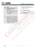
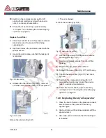
5.3.3
Connection to the compressed
air network
Materials:
◼
Flexible compressed air hose max. 5
ft (1.5 m)
WARNING!
Danger of injury due to
unpredictable movement of the
compressed air hose!
Load switches in the compressed air
network causes jerky movements of