PoE
Status M1 M2
PWR1 PWR2 PoE
1
2
3
4
5
6
7
8
9
10
11
12
13
14
15
16
17
18 19
20 21
22
23
24
24
23
Green=1000M
Yellow=10/100M
On=Link Flashing=A
CT PoE LED:Green=G
ood Supply
Yellow=Over Load
CONSOLE
S3410-24TS-P PoE+
25
26
27
13
14
15
16
17
18
19
20
21
22
23
24
Yellow=Over Load
5
6
7
8
9
10
11
12
On=Link Flashing=A
CT PoE LED M
ode:Green=Good Supply
Yellow=100M
1
2
3
4
Green=10G/5G/2.5G/1G
MGMT
SYS PWR FAN
PoE
PoE FUNC
CONSOLE
LAN
POE
POWER
ACTIVE
Intranet
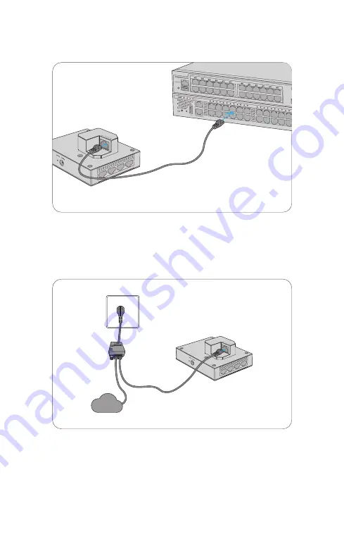
Connecting the PoE Power Supply
Use an Ethernet cable to connect the WAN/PoE port on the AP to the PoE port on a PoE switch.
Use the power cord, power injector and Ethernet cable to connect the WAN/PoE port of the AP
to the local power source.
PoE Switch
PoE Injector


