YFG255 SERIES GAS RETHERMALIZERS
CHAPTER 1: SERVICE PROCEDURES
1-12
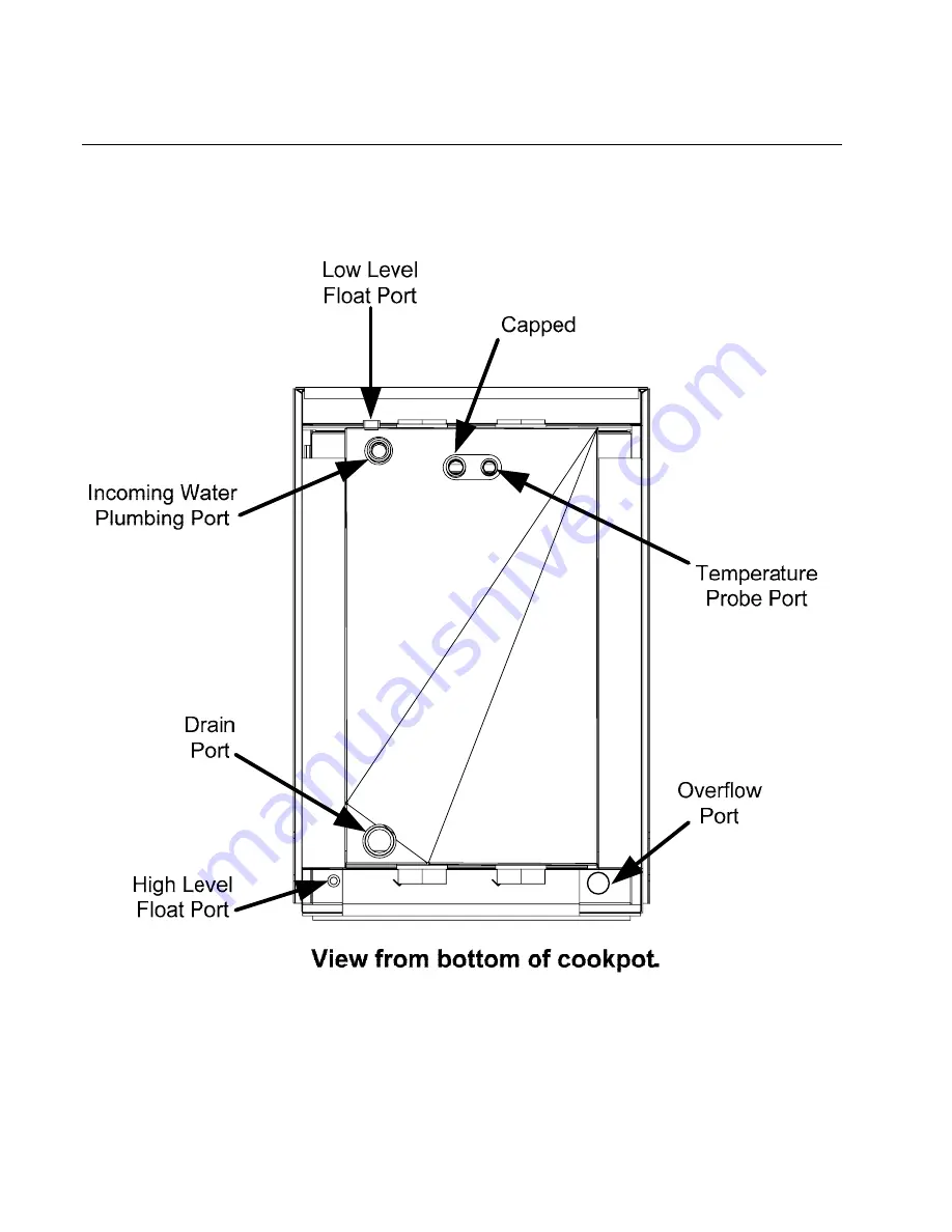
1.5.7 Annotated Cookpot Bottom
Страница 1: ...ercial Food Equipment Service Association recommends using CFESA Certified Technicians www frymaster com 24 Hour Service Hotline 1 800 551 8633 Email service frymaster com 08 2022 8196900 YFG255 Rethe...
Страница 2: ...rt purchased directly from Frymaster or any of its authorized servicers and or the part being used is modified from its original configuration this warranty will be void Further Frymaster and its affi...
Страница 3: ...to cause cancer Inhalation of carbon monoxide is known to the State of California to cause birth defects or other reproductive harm WARNING Do not bang rethermalizer baskets or other utensils on the...
Страница 4: ...1 3 1 5 Replacing Rethermalizer Components 1 4 1 6 Troubleshooting and Problem Isolation 1 13 1 7 Troubleshooting Guides 1 18 1 8 Probe Resistance Chart 1 20 1 9 Wiring Diagram 1 21 2 PARTS LIST 2 1...
Страница 5: ...ith a 24 volt valve system with an electronic ignition system Electronic Ignition Configuration An ignition module connected to an ignitor assembly controls ignition The ignition module performs three...
Страница 6: ...Options YFG255 Series gas rethermalizers are equipped with a factory preset temperature controller These are unique in that the components are wired directly to the controller and do not require an in...
Страница 7: ...ch restraining devices and plug in the electrical cords 1 3 Cleaning the Gas Valve Vent Tube if applicable 1 Set the rethermalizer power switch and the gas valve to the OFF position 2 Carefully unscre...
Страница 8: ...e the rethermalizer power switch and the gas valve in the OFF position Remove the pressure measuring device fitting from the pressure tap hole and reinstall the pressure tap plug 1 5 Replacing Retherm...
Страница 9: ...ater from the cookpot Allow the cookpot to cool completely before proceeding 3 Remove the rethermalizer door for easier access to the temperature probe Lift door up disengage rod from lower door brack...
Страница 10: ...om the connector step 6 Remove the harness insulation The probe can be pulled through the cookpot from the top complete step 7 in this section prior to removing probe 8 Carefully remove the probe from...
Страница 11: ...er back to gain access to the high level float compression nut Removal of a burner may be necessary to access the low level float compression nut 6 Loosen and completely unscrew the compression nut fr...
Страница 12: ...from the pilot mounting bracket and remove the pilot 4 Reverse the procedure to replace the pilot assembly 1 5 6 Replacing the Cookpot 1 Ensure controller and all power switches are off Drain water f...
Страница 13: ...e cap braces to cookpot a nut driver with an extension or long screwdriver is required Use care not to drop the screws into the flues If this happens the screws can be retrieved when the flue is remov...
Страница 14: ...ring removal of the flue cap to cookpot bracket 13 Remove the burner shield Loosen burner bolts two per burner that secure burners to the burner support rail NOTE On most rethermalizers do not remove...
Страница 15: ...damage when cookpot is removed 20 Remove bolts from brackets securing burner manifold to cookpot Leave the manifold in place 21 Using a sharp knife or box cutter cut the silicon seal between and in f...
Страница 16: ...YFG255 SERIES GAS RETHERMALIZERS CHAPTER 1 SERVICE PROCEDURES 1 12 1 5 7 Annotated Cookpot Bottom...
Страница 17: ...assist in identifying some of the more common problems 1 6 1 Ignition Failures Ignition failure occurs when the ignition module fails to sense a flame within the 60 second time delay period and locks...
Страница 18: ...the 24 VAC circuit or pilot system it is most likely in the gas valve itself but before replacing the gas valve refer to the troubleshooting guides in this chapter 1 6 2 Improper Burner Functioning Wi...
Страница 19: ...he kitchen area this indicates that more air is being exhausted than is being replenished and the burners may be starved for air If the rethermalizers gas and air supplies are okay the problem most li...
Страница 20: ...ure in accordance with the procedures in Section 1 4 An obstructed flue which prevents the rethermalizer from properly exhausting may also be the cause Excessively noisy burners especially with flames...
Страница 21: ...h Loctite PST567 sealant or equivalent to prevent leakage In very rare cases a leak may develop along one of the welded edges of the cookpot or where the tube is welded to the cookpot When this occurs...
Страница 22: ...reaker is not tripped C Failed controller C If available substitute a controller known to be working for the suspect controller If the rethermalizer functions correctly order replacement from FAS The...
Страница 23: ...AS Display shows a low temperature and the rethermalizer appears to operate normally A Defective probe A Check temperature probe against standard Minco probe resistance chart on page 1 20 If defective...
Страница 24: ...od but there is not 24 VAC at the gas valve terminals C Inspect temperature probe sensor while still in cookpot for damage Replace if bent dented or cracked Inspect leads for fraying burning breaks an...
Страница 25: ...9 Wiring Diagram Note The diagram in this section depict wiring as of the date of manual publication It may not reflect design changes made to the equipment after publication Refer to the wiring diag...
Страница 26: ...Assembly 230 5472 Handle Door 230 7249 Panel Door 230 7324 Panel Door Liner 810 0275 Spring Door Hinge 810 2346 Magnet Door 4 108 1111 Cover Assembly Cookpot Right includes item 6 5 108 1110 Cover As...
Страница 27: ...26 1117 Caster 5 inch w o Brake Kit includes washers and screws 23 826 1118 Caster 5 inch with Brake Kit includes washers and screws 24 230 8039 Pivot Cover Front 25 220 7231 Box Component 26 230 7383...
Страница 28: ...ression NPT 6 231 8164 Support Hinge Left 7 232 8164 Support Hinge Right 8 230 6251 Baffle Burner 9 230 6301 Bracket Pilot Burner 10 824 2228 Support Burner Manifold 11 810 3221 Manifold Burner 12 810...
Страница 29: ...7 1973 Terminal Post 3 807 0070 Terminal Ground Lug 4 823 7781 Box Transformer 220 7698 Cover Transformer Box 5 108 0959 Assembly Harness 6 826 2787 Kit Controller Digital with Probe and fitting 7 106...
Страница 30: ...HERMALIZERS CHAPTER 2 PARTS LIST 2 5 2 4 Harnesses ITEM PART COMPONENT 1 108 2800 Harness Transformer Solenoid and Float 2 108 2801 Harness Controller Switch and Light 3 108 2802 Harness Ignition Modu...
Страница 31: ...10 3199 Fitting NPT x Tube Hose Barb 3 810 3244 Clamp Hose 4 811 1141 Tubing Clear Plastic ID sold by the foot 5 810 3243 Valve In line Check 6 810 3258 Adaptor Barb x NPT Brass 7 813 0582 Nipple NPT...
Страница 32: ...Front 2 809 0374 Clamp Hose 3 813 0138 Nipple 4 813 0202 Elbow 90 1 5 813 0314 Tee 1 6 813 0525 Barb Fitting 1 Pipe to Hose 7 816 0779 Hose Drain 10 25 8 816 0787 Hose Drain 6 75 9 823 7649 Plate Asse...
Страница 33: ...3722 Clamp Pipe Heavy 5 813 0066 Elbow NPT 90 6 813 0096 Nipple x 6 00 NPT 7 813 0112 Nipple x 2 00 NPT 8 813 0114 Nipple x 2 50 NPT 9 813 0174 Union NPT 10 813 0251 Nipple x 4 50 NPT 11 813 0257 Nipp...
Страница 34: ...6 x inch Phillips Head NP 809 0359 Screw 8 x inch Hex Washer Head 809 0360 Screw 8 x inch Hex Washer Slot Head 826 1371 Screw 8 x inch Hex Head ZP Pkg of 25 809 0361 809 0818 Screw 8 x inch Type B 80...
Страница 35: ...THIS PAGE INTENTIONALLY LEFT BLANK...
Страница 36: ...improvement may necessitate change of specifications without notice Part Number FRY_IOSP_8196900 08 2022 Welbilt offers fully integrated kitchen systems and our products are backed by KitchenCare afte...