


FrSky Electronic Co., Ltd
Website:www.frsky-rc.com E-mail:[email protected] Technical Support: [email protected]
FrSky Electronic Co., Ltd
Website:www.frsky-rc.com E-mail: [email protected] Technical Support: [email protected]
1. Introduction
www.frsky-rc.com
www.frsky-rc.com
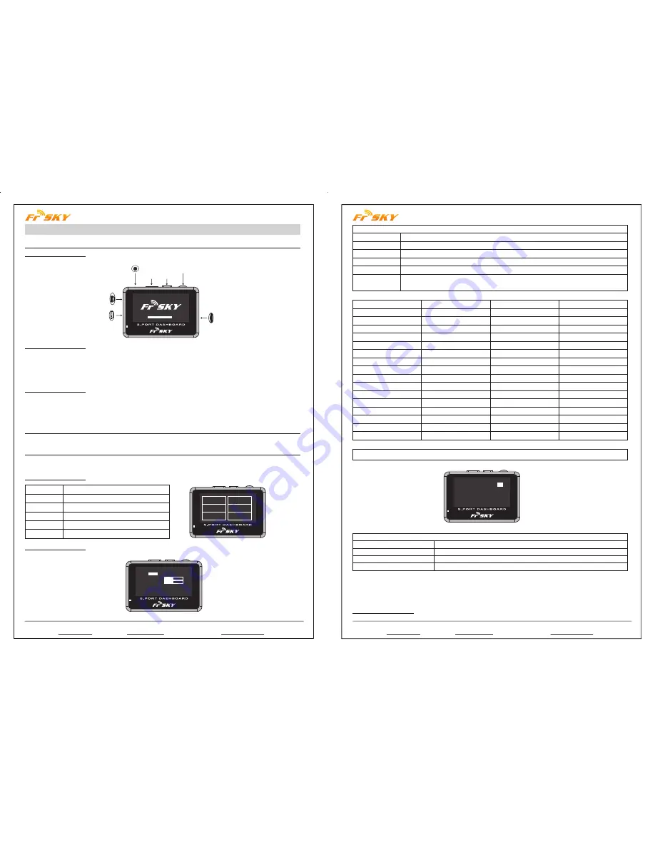
2. Installation
3. Screen Structures
1.1 Overview:
1.2 Specifications:
1.3 Features:
3.1 Main screen:
3.2 SYSTEM screen:
Instruction Manual for FrSky S.Port Dashboard
Earphone Part
Page Power Switch
Rotate Switch
TF Card Slot
USB Port
-
+
S.Port
Model Names: FSD (FrSky S.Port Dashboard)
Compatibility: FrSky X Series Telemetry Modules
Voltage Range: 4.8~6V
Dimension: 75*50*13.8mm
Pixel: 128*64
1) Show all connected sensors data;
2) Capable of programming alarm thresholds and system settings;
3) Set Physical ID and Group Number for S.Port sensors;
4) Firmware upgradeable for all S.Port products.
Connect FrSky FSD to the S.Port on FrSky X series telemetry module (S.Port, VCC, GND) by the provided cable.
Use “rotate switch” to choose, short press “rotate switch” to confirm, short press “page” to the next page, hold
“page” for 1 second to go back to previous screen.
SYSTEM
VOICES
UPDATE
DATA
IDSET
INFO
System settings
Settings
Upgrade S.Port devices
Telemetry data display
Set phyID and GNum for S.Port sensors
Firmware and Eeprom version
System Set
Units
Contrast
Volume
Log Interval
Time Zone
SYSTEM
DATA
IDSET
INFO
VOICES
UPDATE
*System Set
Units:
metric
celcius
Contrast:
Volume:
Log Interval: 1s
Time Zone: 000
Alarm: Height Dis < 000
-
-
+
+
metric or imperial (selectable), fahrenheit or celcius (selectable)
adjust the contrast of the screen
adjust the volume of the voice
data log period (0.1s, 0.5s, 1s, 2s, 5s selectable)
-11 to 12 time zone selectable (”-” is west and “+ ”is east)
use “rotate switch” to choose, short press “rotate switch” to change the setting
(see detailed chart below)
Alarm
Alarm
Height
HeightC
A1
A1C
A2
A2C
A3
A3C
A4
A4C
RxBat
RxBatC
SWR
SWRC
RSSI
RSSIC
Sensor
Variometer
Variometer
Receiver
Receiver
Receiver
Receiver
S.Port2UART
S.Port2UART
S.Port2UART
S.Port2UART
Receiver
Receiver
Module
Module
Receiver
Receiver
Direction
>
>
<
<
<
<
<
<
<
<
<
<
>
>
<
<
Unit
10m
10m
0.1V
0.1V
0.1V
0.1V
0.1V
0.1V
0.1V
0.1V
0.1V
0.1V
Note: “C” after the alarm name means “critical”.
*Sensor Set
RPM Sensor blade:
02
Anolog Sensor
Volt ratio:
04 04 04 04 04
GPS Sensor Enabled
Flvss Sensor Enabled
Sensor Set
RPM Sensor blade
Anolog Sensor Volt ratio
GPS Sensor
Flvss Sensor
Set the blade numbers for RPM Sensor
Voltage Division Ratio for A1, A2, A3, A4, RBat
Enable or Disable the GPS data screen (Page 4 of DATA screen)
Enable or Disable the Lipo Voltage data screen (Page 5 of DATA screen)
Follow the steps below to change “System Set” and “Sensor Set”:
Step 1: Short press “rotate switch” to open “system set”;
Step 2: Use “rotate switch” to choose the position you want to change;
Step 3: Short press “rotate switch” to change the settings.
3.3 VOICES screen:


