background image

Page 8 


rev 2.0.03


6.2


Calibrating the servos 

In this section you’ll calibrate the servos. The goals are: 


Maximise control surface movements  


Achieve a left/right symmetry regardless of linkage differences 


Linearise responses.  

All the adjustments in this section are made in CAL mode. 

Note:

 correct calibration is essential for diff to work correctly, and for precise tracking of flaps with ailerons.  

6.2.1


Prepare for calibration 


Switch on the transmitter (do not power up the receiver yet) 


Enter CAL mode, and set switch 

SA

 to middle. 


Power up the receiver 


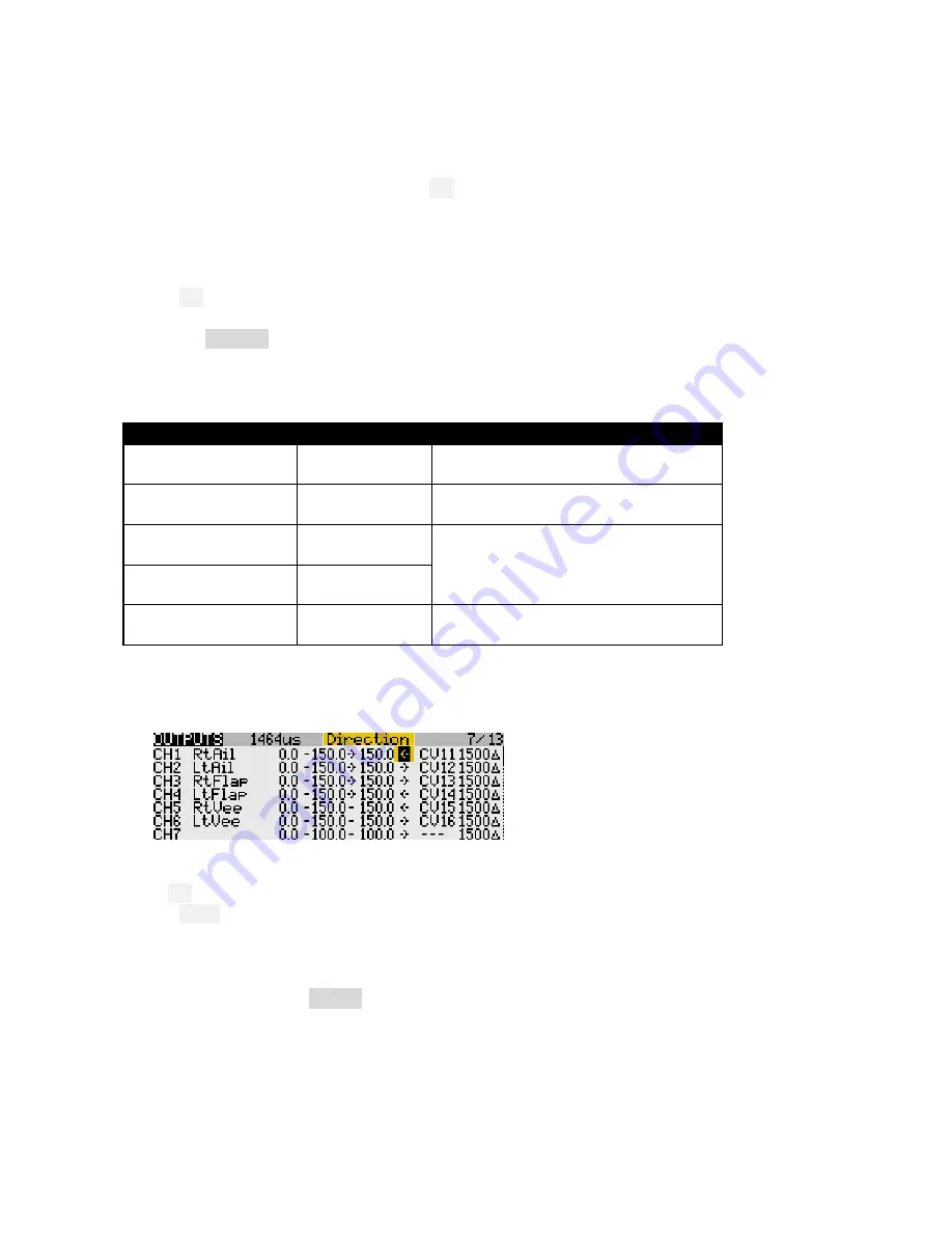
Open the 

OUTPUTS

  menu 

6.2.2


Set servo rotation 


Set the servo rotation according to table below. Pay attention to notes regarding aileron and elevator. 

Stick command 

Control surface 

Notes 

Aileron stick right →


RtAil goes up ↑ 
LtAil goes up↑ 

In CAL mode,

 ailerons move together!! 

Thr stick forward ↑


RtFlap goes up↑ 
LtFlap goes up↑ 

Ignore any “invert throttle” message  
when reversing an output. 

V-TAIL only:  
Ele stick forward ↑


RtVee goes up ↑ 
LtVee goes up ↑ 

In CAL mode,

 elevator(s) operate in 

reverse to normal!!


X-TAIL only:  
Ele stick forward ↑


Ele goes up ↑ 

X-TAIL only:  
Rudder stick right →


Rud goes right 


To change the direction of an output: 
1.


Skip to the Direction field  

2.


Press 

{

ENTER

}

, and immediately 

{

EXIT

}


Finally, check operation as follows: 


Exit CAL  


Enter Cruise mode. 


Check for correct direction of aileron, elevator and rudder (note: the flaps cannot be checked yet). 

6.2.3


Calibrate servo end-points and centres 

In this section you’ll use the 

OUTPUTS

 menu to adjust the end points and centres of the servos. When setting 

end-points, consider all inputs affecting the servo. For example, flap movement should be allow for crow 
and aileron inputs. Otherwise a servo may stop dead before the commanded position is reached, resulting 
in deadband at the stick (sometimes this will be unavoidable – or even desirable!). 

If you don’t know the movements required for your model, then set servo end-points to maximum subject to 
restrictions below. 
New in version 2

: calibration uses curves. 

Leave min/max/subtrim at -150/150/0. 


Содержание E-Soar

Страница 1: ...Copyright Michael Shellim E Soar for FrSky Taranis and Horus Version 2 0 Setup Guide Mike Shellim 8 Feb 2017...

Страница 2: ...3 Control remapping X9E Horus 7 6 1 4 Familiarisation 7 6 2 Calibrating the servos 8 6 2 1 Prepare for calibration 8 6 2 2 Set servo rotation 8 6 2 3 Calibrate servo end points and centres 8 6 2 4 Bac...

Страница 3: ...r_20x eepe EEPROM images for V and X T tail esr_ wav Sound files 1 2 Requirements The following will be required FrSky Taranis or Horus transmitter OpenTx version 2 1 2 2 see change log for recommende...

Страница 4: ...Stick and switch assignments Stick assignments mode1 mode4 are set in MODEL SETUP STICK MODE Functions are assigned as follows Control Function Throttle stick Spoiler Throttle trim Spoiler compensati...

Страница 5: ...Diff settings are stored per flight mode Roll rate enhancement Aileron diff reduces to zero as spoiler is deployed This helps with roll response under crow An adjustable Reverse diff mix further impr...

Страница 6: ...ixers and trims are disabled To enable CAL mode 1 Apply full left aileron and full up elevator and hold 2 Pull SH 3 Release SH 4 Release stick s When CAL mode is enabled a beep sounds every 5 secs and...

Страница 7: ...ck on new model and choose Use as Default From the File menu choose WRITE MODELS AND SETTINGS TO RADIO Close OpenTx Companion 6 1 2 Stick calibration Important Your sticks must be properly calibrated...

Страница 8: ...sing an output V TAIL only Ele stick forward RtVee goes up LtVee goes up In CAL mode elevator s operate in reverse to normal X TAIL only Ele stick forward Ele goes up X TAIL only Rudder stick right Ru...

Страница 9: ...exactly match the left flap 5 stick fully back adjust point 1 6 stick back adjust point 2 7 stick to centre adjust point 3 8 stick to forward adjust point 4 9 stick fully forward adjust point 5 To mat...

Страница 10: ...ENTER to open curve editor 5 Move aileron stick to centre Set Point 2 for correct centre 6 Move aileron stick right Set point 3 to desired upper limit allowing for both crow and aileron movement 7 Mov...

Страница 11: ...appropriate weight and expo Flight mode numbers as follows 0 Thermal 2 Power 3 Landing 4 Cruise Safety note The CATCHALL line must have all flight modes enabled no switch and Important it must be the...

Страница 12: ...at end points In this step you will set nominal camber Start with flaps 1 Enable Thermal mode 2 Move RS to centre position 3 Open GLOBALVARS menu 4 Adjust GV2 FM0 as required 5 For ailerons repeat 2 4...

Страница 13: ...follows 1 Enter landing mode 2 Apply minimum spoiler adjust elevator trim 3 Apply full spoiler adjust throttle trim Note After intial flight tests you can fine tune the response by editing Curve 2 Sp...

Страница 14: ...of Spoiler and Flap Spoiler and flap functions may be assigned to any suitable control Recommended options for the Taranis X9D are as follows Function Assign to Default Menu point Spoiler Thr LS or R...

Страница 15: ...becomes active and OpenTx uses those rate expo values If there is no match OpenTx advances to the next line and repeats the test And so on till either a match is found or the end of the list is reach...

Страница 16: ...own modifications please study the Excel documentation carefully and make sure you understand the implications of any changes Recommended workflow as follows 1 Setup your model first as described in...

Отзывы: