Frontier SB1388 Скачать руководство пользователя страница 58

TORQUE SPECIFICATION TABLE 

OM 0437SB1388-A 

56


G

ENERAL SPECIFICATION TABLE


U

SE THE FOLLOWING TORQUES WHEN SPECIAL TORQUES ARE NOT GIVEN


Note:These values apply fasteners as received from supplier dry, or when lubricated with normal engine oil. They do not apply if 

special graphited or moly sidulphide greases or other extreme pressure lubricants are used. These values apply to dry 
conditions; under lubricated conditions reduce by 25% the torques in this table. 


B

OLT HEAD 

I

DENTIFICATION


INCHES 

Bolt Size 


Grade 2


Grade 5 


Grade 8 


METRIC 

Bolt Size 


Class 5.8


Class 8.8


Class 10.9


in-tpi 

1


N-m 

2


lbs-ft 

3


N-m lbs-ft N-m lbs-ft 


mm

x

pitch 

4

 N-m lbs-ft N-m lbs-ft N-m lbs-ft 

1/4" – 20NC 

7.4 

5.6 

11 

16 

12 

  M 5 X 0.8 

6 5 9 

1/4" – 

28NF  8.5 6  13 10 18 

14 

  M 6 X 1 

11 8  15 

11 

5/16" – 

18NC 15 11 24 17 33 

25 

  M 8 X 1.25 

17 

12 

26 19 36 

27 

5/16" – 

24NF 17 13 26 19 37 

27 

  M 8 X 1 

18 

13 

28 21 39 

29 

3/8" – 

16NC  27 20 42 31 59 

44 

  M10 X 1.5 

33 

24 

52 39 72 

53 

3/8" – 

24NF  31 22 47 35 67 

49 

  M10 X 0.75 

39 

29 

61 45 85 

62 

7/16" – 

14NC 43 32 67 49 95 

70 

  M12 X 1.75 

58 

42 

91 67 125 

93 

7/16" – 

20NF 49 36 75 55 105 

78 

  M12 X 1.5 

60 

44 

95 70 130 

97 

1/2" – 

13NC  66 49 105 76 145 

105 

  M12 X 1 

90 

66 

105 77  145 

105 

1/2" – 

20NF  75 55 115 85 165 

120 

  M14 X 2 

92 

68 

145 105 200 

150 

9/16" – 

12NC  95  70  150 110 210 

155 

  M14 X 1.5 

99 

73 

155 115 215 

160 

9/16" – 

18NF  105 79  165 120 235 

170 

  M16 X 2 

145 

105 

225 165 315 

230 

5/8" – 

11NC  130 97  205 150 285 

210 

  M16 X 1.5 

155 

115 

240 180 335 

245 

5/8" – 

18NF  150 110 230 170 325 

240 

  M18 X 2.5 

195 

145 

310 230 405 

300 

3/4" – 

10NC  235 170 360 265 510 

375 

  M18 X 1.5 

220 

165 

350 260 485 

355 

3/4" – 

16NF  260 190 405 295 570 

420 

  M20 X 2.5 

280 

205 

440 325 610 

450 

7/8" – 

9NC 

225 165 585 430 820 

605 

  M20 X 1.5 

310 

230 

650 480 900 

665 

7/8" – 

14NF  250 185 640 475 905 

670 

  M24 X 3 

480 

355 

760 560 1050 

780 

1" – 

8NC 

340 250 875 645 1230 

910 

  M24 X 2 

525 

390 

830 610 1150 

845 

1" – 

12NF 

370 275 955 705 1350 

995 

  M30 X 3.5 

960 

705 

1510 1120 

2100 

1550 

1 1/8" – 

7NC  480 355 1080 795 1750 

1290 

  M30 X 2 

1060 

785 

1680 1240 

2320 

1710 

1 1/8" – 

12NF 540 395 1210 890 1960 

1440 

  M36 X 3.5 

1730 

1270 2650 1950 

3660 

2700 

1 1/4" – 

7NC  680  500  1520 1120 2460 

1820 

  M36 X 2 

1880 

1380 2960 2190 

4100 

3220 

1 1/4" – 12NF 

750 

555 

1680 

1240 

2730 

2010 


1


in-tpi = 

nominal thread diameter in inches-threads per inch


2


N-m = newton-meters


lbs-ft= pounds-foot


4


mm x pitch = nominal thread diameter in millimeters x thread Pitch


1 3/8" – 

6NC  890  655  1990 1470 3230 

2380 


1 3/8" – 

12NF  1010 745  2270 1670 3680 

2710 


1 1/2" – 

6NC  1180 870  2640 1950 4290 

3160 


1 1/2" – 

12NF  1330 980  2970 2190 4820 

3560 


*Torque tol0%, -15% of torquing values. Unless otherwise specified use torque values listed above 


5.8 

8.8 

10.9

Содержание SB1388

Страница 1: ...OM0437SB1388 Rev1 11 15 Serial 1XFSB13X_E0140001 plus OPERATOR S MANUAL SNOWBLOWER SB1388...

Страница 2: ......

Страница 3: ...hute and the Hydraulic Rotation 15 Installation of the 5RDF0071 Hydraulic Deflector for 2 part Chute 16 Installation of the Hydraulic Hoses 17 A Hoses of the chute rotation 17 B Hoses of the chute def...

Страница 4: ...arbolts 32 Driveshaft 32 Driveline 32 Chain Idler Adjustment 33 Lubrication 34 Driveline Troubleshooting 35 37 PARTS 38 55 Introduction 38 Manual Holder 38 Chain Idler 39 Snowblower Assembly Front Par...

Страница 5: ...m No Rotation of drum N A Flow restrictor N A Housing Housing thickness 11 Ga Side panel thickness 1 4 Impeller housing thickness 1 4 Chute Chute position Right Rotation of the chute Hydraulic by moto...

Страница 6: ...ned in this manual and those labeled on the implements and on the tractor Follow the safety recommendations and make sure that those with whom you work follow them Illustrations The illustrations may...

Страница 7: ...ever carry children while operating the machine They may fall off and be seriously injured or interfere with safe operation of the machine 5 Never allow children to play on the machine or attachment e...

Страница 8: ...e clutch and shift into neutral before starting the engine 5 Do not operate equipment in wintertime without wearing adequate winter garments 6 Never attempt to make any adjustments while engine is run...

Страница 9: ...O stop the engine immediately and check for cause Excessive vibration is generally a sign of holeble 11 Do not run the engine indoors except when starting engine and transporting attachment in or out...

Страница 10: ...tween the tractor and the primary implement PTO drive shaft that will allow a 1000 rpm tractor shaft to power a 540 rpm implement at speeds higher than 540 rpm 5 To use the blower with PTO at 1000 rev...

Страница 11: ...el tank outdoors with extreme care Never fill fuel tank indoors Replace fuel cap securely and wipe up spilled fuel 13 Never allow anyone to operate the snowblower until they are thoroughly familiar wi...

Страница 12: ...ating functions If you have questions concerning modifications consult with your dealer 11 Do not operate a snowblower that is defective or has missing parts Make sure that all recommended maintenance...

Страница 13: ...SAFETY DECALS OM 0437SB1388 A 11 Replace immediately if damaged...

Страница 14: ...SAFETY DECALS OM 0437SB1388 A 12 Replace immediately if damaged...

Страница 15: ...uts into various sizes After assembly torque all the bolts according to the Torque Specification Table at the end of the manual Installation of the Slow Motion Vehicle Sign if not installed Figures 1...

Страница 16: ...NC x 5 1 2 bolts 3 4 lockwashers and 3 4 nylon insert lock nuts items 3 4 5 2 Figure 3 Install the brace item 6 under the lower hitches item 1 with two 7 8 NC x 5 bolts item 7 lockwashers and nylon i...

Страница 17: ...i friction plate s assembly item 2 5 Figure 6 Place the chute guide item 3 on the chute base item 1 Then install the retaining plate item 4 using two 1 2 NC x 1 1 2 bolts 1 2 lockwashers and 1 2 NC ny...

Страница 18: ...Figure 9 Install the hose support item 7 using two 5 16 NC x 1 serrated flange bolts and 5 16 NC serrated flange nuts items 8 9 8 Figure 9 Attach the hose clamp item 11 with a 3 8 NC x 1 1 2 bolt and...

Страница 19: ...t and a 3 8 NC nylon insert lock nut items 3 4 5 3 Make sure the hoses are not too tight between the hydraulic motors and the hose support and do not touch sharp edges B HOSES OF THE CHUTE DEFLECTOR I...

Страница 20: ...of the chute and that the radius of curvature of the hoses remains correct Also make sure they do not cross and they do not rub against sharp edges Rotate the chute and move the deflector to ensure th...

Страница 21: ...e Torque Specification Table at the end of the manual 5 On the upper auger install the sprocket 1 1 4 3 1 2 c c holes item 3 using four 3 8 NC x 1 1 2 bolts lockwashers and nylon insert lock nuts item...

Страница 22: ...e serrrated auger and secure with four 7 16 NC X 1 1 2 bolts lockwashers and nylon insert lock nuts items 12 13 14 5 Slide the spacer item 10 and the flange bearings items 9 on the serrated auger Do n...

Страница 23: ...Stainless Skid Shoes 5RDF0062 OPTION Figure 15 15a 1 Figure 15 Remove the 5 16 NC x 1 1 2 bolt and 5 16 NC nylon insert locknut items 4 5 2 Figure 15 Remove the round wire lock pin and the L pin item...

Страница 24: ...he 7 8 NC stover lock nut items 6 7 2 Remove the brace by removing the 7 8 NC x 5 bolt 7 8 lockwasher and 7 8 NC nut items 8 9 10 3 Remove the lower three point hitches item 1 by removing the two vert...

Страница 25: ...item 4 3 To level snowblower front to back adjust using the tractor adjustable arm item 3 4 To level side to side use leveling crank on right lower lift arm 5 Set the tractor anti sway turnbuckles so...

Страница 26: ...ower hitch plates and secure with the linchpins item 4 as illustrated 2 Install the 1 x 6 1 16 lg Cat 2 hitch pin item 5 in the lower holes of the upper hitch by first inserting a bushing 1 1 4 ext x...

Страница 27: ...he snowblower and the tractor Angles of Driveline Joints Too Large Avoid Reasonable Angles of Driveline Joints Acceptable Unequal Angles at Driveline Joints Avoid Equal Angles at Driveline Joints Reco...

Страница 28: ...mine the L length for your tractor model first find the X factor by measuring the horizontal distance between the end of the tractor s drive shaft and the end of the snowblower s driven shaft when the...

Страница 29: ...alf shaft guard as shown on figure 21 4 Cut off inner and outer guard tubes as well as the inner and outer telescopic sections 5 Cut the guard a second time leaving the same distance between the end o...

Страница 30: ...driveline safety chain to the tractor appropriate location and the other to the three point hitch brace item 3 to prevent the driveline shield from rotating NOTE Depending on trac tor used it may be n...

Страница 31: ...und speed will range from 4 to 7 MPH for light dry snowfalls 3 to 6 inches and 1 to 3 MPH for heavy wet or drifted snow To transport disengage the drive shaft and raise the snowblower to full transpor...

Страница 32: ...1 and the L pin item 2 and do the following settings Clearance between cutting edge and surface Level paved surface Adjust to 1 16 to 1 8 Uneven or gravel surface Adjust to 1 2 and more according to s...

Страница 33: ...aft shut off the tractor engine remove the ignition key wait for all movement to stop and then clear the snow from the chute A definite pattern of operation is required to thoroughly clean the snow ar...

Страница 34: ...re bolts are located on the chain cover of the snowblower If the bolts have to be replaced use these parts only Driveshaft Shearbolt hex 3 8 NC x 1 1 4 lg 3 8 NC nut and 3 8 lockwasher Part 5RD668029...

Страница 35: ...top of the sprocket to underneath the side plate 2 That distance must be of 2 1 8 minimum if less than 2 1 8 the chain is too much stretched and may cause premature wear of the sprockets It needs to...

Страница 36: ...ve collar Chain 4 hours and after each operation Lubricate with chain lube Drive Shaft 24 hours Grease fitting on shear plate and the gearbox coupler Gearbox very month Check oil level If needed add A...

Страница 37: ...nect pins must be cleaned and greased every 16 hours AVOIDABLE DAMAGES POSSIBLE CAUSES CORRECTIVE ACTIONS YOKE Yoke ears deformation Excessive shaft length Axial loads too high Excessive working angle...

Страница 38: ...greasing Verify compatibility between shaft and working conditions Carefully follow greasing instructions Replace defective cross bearings Note Cross bearings must be greased every 8 working hours AVO...

Страница 39: ...parts of the machine or tractor Mount chain to allow maximum angularity Replace defective parts Shield cone damaged Shield cone in contact with components on the tractor and or implement Excessive an...

Страница 40: ...are that is available at your local hardware supply Right Hand and Left Hand are determined by those seen by the conductor standing behind the equipment The manufacturer reserves the rights to change...

Страница 41: ...6 Compression spring 1 5RD664876 7 Plastic bushing 1 5RD4300124 8 Bolt hex 3 8 NC x 1 Gr 5 PTD 2 O L 9 Shoulder screw 5 8 NC x 1 2 1 5RD3200023 10 Bolt hex 3 4 NC x 2 3 4 Gr 5 PTD 2 O L 11 Lockwasher...

Страница 42: ...PARTS OM 0437SB1388 A 40 SNOWBLOWER ASSEMBLY FRONT PART...

Страница 43: ...0A28 1 5RD3300054 14 Plow bolt 7 16 NC x 1 1 2 Gr 5 PTD 11 5RD0400011 15 Bolt hex 1 4 NC x 1 Gr 5 PTD 4 O L 16 Bolt hex 7 16 NC x 1 1 2 Gr 5 PTD 4 O L 17 Bolt hex 1 2 NC x 1 1 2 Gr 5 PTD 8 O L 18 Bolt...

Страница 44: ...PARTS OM 0437SB1388 A 42 SNOWBLOWER ASSEMBLY REAR PART...

Страница 45: ...Lock nut 5 5RD668029 21 Shearbolt incl Nut 2 5RD657199 22 Flat washer nylon 7 16 4 5RD658468 23 Round wire lockpin 1 4 x 2 2 5RD1900006 24 Bolt hex 5 16 NC x 1 1 2 Gr 5 PTD 2 O L 25 Bolt hex 7 16 NC x...

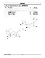
Страница 46: ...PARTS OM 0437SB1388 A 44 THREE POINT HITCH...

Страница 47: ...6 lg Cat 2 1 5RD4600052 10 Linchpin 7 16 PTD 3 5RD1900003 11 Hose clamp 2 5RD666583 12 Bolt hex 3 8 NC x 1 3 4 Gr 5 PTD 1 O L 13 Bolt hex 3 4 NC x 5 1 2 Gr 5 PTD 6 O L 14 Bolt hex 7 8 NC x 2 1 2 Gr 5...

Страница 48: ...lt 1 4 NC x 1 GR 5 PTD for motor M S 1 O L 3 Lockwasher 5 16 PTD for motor Eagle 1 O L Lockwasher 1 4 PTD for motor M S 1 O L 4 Flat washer 5 16 3 8 hole PTD for motor Eagle 1 O L Flat washer 1 4 5 16...

Страница 49: ...5RD663144 7 Yoke and hub assembly 1 5RD663145 8 Bolt and nut 2 5RD662199 9 Grease fitting 1 5RD663148 10 Ball 24 5RD663162 11 Shear bolt and nut M10 x 1 5 x 55 mm gr 8 8 PTD 1 5RD657199 12 Shields wi...

Страница 50: ...ring 1 5RD659844 6 Spacer 1 5RD656648 7 Internal retaining ring 1 5RD656654 8 Bearing 1 5RD656647 9 Shaft 1 5RD656651 10 Gear 1 5RD656645 11 External retaining ring 1 5RD656646 12 Bearing 2 5RD656641...

Страница 51: ...662195 WORM GEAR BOX 5RD662195 REF DESCRIPTION QTY PART Gear Box assembly 1 5RD662195 1 Seal kit 35 x 72 x 10 1 5RD659845 2 Bearing 1 5RD659844 3 Bearing 1 5RD656647 4 Bearing 2 5RD656641 5 Seal kit...

Страница 52: ...Chute base 1 5RD671009 2 Deflector 1 5RD671008 3 Hinge pin 1 5RD670884 4 Adjustment tube 1 5RD654076 5 Adjustment rod 1 5RD654074 6 Grease fitting 1 4 NF 3 5RD654106 7 Stover lock nut 1 2 NC PTD 1 O...

Страница 53: ...T male 2 5RD656480 10 Dust cap 2 5RD664898 11 Flow restrictor 90 elbow 3 8 NPT M x 3 8 NPT SWF 2 5RD3900204 12 Plastic bushing 4 5RD4300124 13 Flat washer 9 16 PTD 4 O L 14 Cotter pin 1 8 x 1 1 4 4 O...

Страница 54: ...0 elbow 3 8 NPT M x 3 8 NPT SWF 2 5RD3900204 4 Hose 3 8 x 140 2 5RD3700270 5 Quick coupler 1 2 NPT male 2 5RD656480 6 Dust cap 2 5RD664898 7 Hose clamp double 2 5RD666583 8 Bolt hex 3 8 NC x 1 1 2 Gr...

Страница 55: ...K HITCH 5RDF0077 REF DESCRIPTION QTY PART 1 Lower hitch 2 5RD671069 2 Pin Cat 2 1 1 8 x 6 1 4 PTD 2 5RD4600042 3 Lower bushing CAT 2 2 5RD668608 4 Upper bushing CAT 2 2 5RD668607 5 Spring pin 5 16 X 2...

Страница 56: ...1 1 4 4 holes 2 5RD4300118 9 Chain 60 x 88 links connecting link 1 5RD3300059 10 Connecting link 60 1 5RD654839 11 Bolt hex 1 2 NC x 1 1 4 PTD 3 O L 12 Bolt hex 3 8 NC x 1 1 4 PTD 2 O L 13 Bolt hex 3...

Страница 57: ...x 1 3 4 Gr 5 PTD incl in the kit 8 5RD0400030 4 Lockwasher 1 2 PTD incl in the kit 8 O L 5 Nut hex 1 2 NC PTD incl in the kit 8 O L 6 STAINLESS SKID SHOES 1 5RDF0062 7 CUTTING EDGE CHT400 1 5RDF0050...

Страница 58: ...X 2 92 68 145 105 200 150 9 16 12NC 95 70 150 110 210 155 M14 X 1 5 99 73 155 115 215 160 9 16 18NF 105 79 165 120 235 170 M16 X 2 145 105 225 165 315 230 5 8 11NC 130 97 205 150 285 210 M16 X 1 5 155...

Страница 59: ......

Страница 60: ...All Rights Reserved PART NO 5RDSB1388A3...

Отзывы: