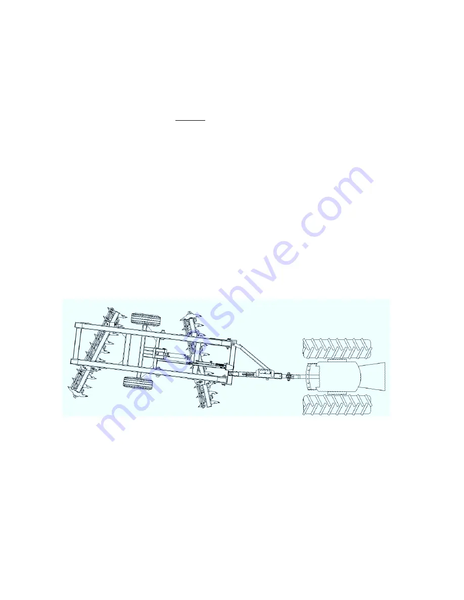
Operating the Disk
General Operating Guidelines
□
Use the recommended size tractor. Weight is as important as horsepower. Too light a tractor will
be overpowered by the plowing action of the disk and its front end will be swung to the left,
requiring constant steering corrections.
□ Always raise the disk out of the ground before turning. If pulling a harrow, roller or other toolbar
behind the disk, raise the disk just clear of the ground before turning.
□ In the field do not back-up with the disk in the fully raised position. This will prevent the disk from
overbalancing to the rear which may damage the control arms.
□ Speed, depth and soil type all determine how level the ground left behind the disk. To minimize
ridging or gouging, limit the disking speed to 4-6 mph.
□ On tractors equipped with a swinging drawbar, allow the drawbar some movement when working
in level or gently rolling fields. In severely rocky conditions, heavy clay or tree stumps allow more
swing in the drawbar. In all other conditions, lock the drawbar in the center position.
□ Pulling a drag or heavy harrow behind the disk can reduce side draft and aid in levelling the soil.
Disk Adjustments
All single offset disks have a single characteristic in common. Because the front gang of disk blades
are set at an angle to their direction of movement and because these blades are working in “new”
ground compared to the rear disks which are working in ground already partially tilled by the front
blades, a single offset disk tries to rotate clockwise as it is pulled forward through the field. To
perform optimally and to reduce stress and premature wear on components, it is desirable that the
machine draft in a straight line behind the tractor. As well, the concavity of the disk blades is such
that in the center angle setting the blades will accomplish the most tillage with the least horsepower
and minimum wear to the blades. When the disk drafts to one side (i.e. “dog tracking” or “crabbing”)
the gang angles are changed and the quality of the tillage suffers.
There are three types of adjustments that affect the draft of the disk.
REPOSITION THE HITCH.
This adjustment is best accomplished when the disk is not attached to the tractor. Support the bridle
crossbar to which the hitch and side arm are attached with a jack and stand. Alternatively the head
of the bridle mast can be chained back to the first member of the main frame. Next loosen the large
fabricated bolt and the 1-1/4” bolt attaching the hitch and side arm to the bridle. Remove the 1-1/4”
bolt attaching the side arm to the plates on the side of the hitch.
The hitch bar can be placed in five fixed positions. Moving the hitch towards “L” as illustrated will
cause the rear of the disk to move to the left when viewed from behind. Moving towards “R” will
cause the rear of the disk to move to the right when viewed from behind.
15


