


9
EN
network of the Fronius Symo Hybrid because this emergency power network has a fre-
quency of 53 Hz.
Transition from
feeding energy
into the grid to
emergency power
mode
1.
The public grid is monitored by the inverter's internal grid and system protection unit
and by the Fronius Smart Meter connected to it.
2.
Failure of the public grid
3.
The inverter carries out the necessary measures according to the country standard
and then switches off.
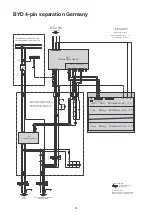
Contactors K1 and K2, as well as K4 and K5, drop out. This disconnects the emergen-
cy power circuits and the inverter from the rest of the home network and from the pub-
lic grid, as the main contacts of the contactors K1 and K2 open at all pins. The NC
auxiliary contacts of contactors K1 and K2 send feedback to the inverter that the con-
tactors are open (a condition for starting the emergency power mode).
4.
The NC main contacts of contactors K4 and K5 are closed, establishing a connection
between the neutral conductor and the ground conductor. The two other NC main con-
tacts of contactors K4 and K5 give feedback to the inverter that the ground connection
has been established correctly (a condition for starting the emergency power mode).
5.
The inverter activates relay K3, which interrupts the supply to contactors K1, K2, K4
and K5. This prevents unintentional activation of contactors K1, K2, K4 and K5 and
thus a grid connection when voltage is restored in the grid.
6.
The NO contact of relay K3 gives additional feedback to the inverter on whether the
locking was successfully performed by relay K3.
7.
The inverter decides based on the contactors' feedback as well as the measurements
on the inverter terminals and the Smart Meter that the emergency power mode can be
activated.
8.
The inverter starts emergency power mode after a defined checking period
9.
All loads in the emergency power circuits are supplied with power. The remaining
loads are not supplied with power and are safely isolated.
Transition from
emergency power
mode to feeding
energy into the
grid
1.
The inverter is operating in emergency power mode. The contactors K1 and K2 to the
public grid are open.
2.
Public grid available again
3.
The Fronius Smart Meter monitors the grid parameters on the public grid and passes
this information to the inverter.
4.
After a defined measuring period, the restored public grid is deemed to be stable.
5.
The inverter ends emergency power mode and disconnects the outputs.
6.
The inverter deactivates K3. The contactors K1, K2, K4 and K5 are reactivated.
7.
All circuits are reconnected to the public grid and are supplied by the grid. The inverter,
therefore, does not feed anything into the grid.
8.
The inverter can start feeding energy into the grid again after performing the grid
checks required by the country standard.


