


6
Cabling variants including emergency power cir-
cuits and 3-pin separation e.g. Austria or Australia
Circuit diagram
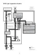
The circuit diagram for the cabling variant "3-pin separation Austria" can be found in the
appendix to this document on page
12
.
The circuit diagram for the cabling variant "3-pin separation Australia" can be found in the
appendix to this document on page
13
.
Functions
-
Measuring and transferring the required parameters for energy management and So-
lar.web by the Fronius Smart Meter
-
Disconnecting from the public grid to enable operation in emergency power mode if
the grid parameters are outside the country-specific standards.
-
Reconnecting to the public grid when the grid parameters are within the limits speci-
fied by the country-specific standards.
-
Option of having a separate emergency power circuit or several emergency power cir-
cuits that are supplied even during failure of the public grid. The total load of the emer-
gency power circuits must not exceed the nominal output of the inverter. Furthermore,
the performance of the attached battery must also be considered. The other circuits
are not supplied in the event of a power failure.
Cabling for emer-
gency power cir-
cuit and non-
emergency power
circuits
The use of contactor K2 is optional in Australia.
If not all the consumers in the home need to be supplied in an emergency power situation,
the circuits need to be divided into emergency power circuits and non-emergency power
circuits.
The total load of the emergency power circuits must not exceed the nominal output of the
inverter.
The emergency power circuits and non-emergency power circuits must be fused separate-
ly according to the required safety measures (residual-current circuit breaker, automatic
circuit breaker, etc.).
In emergency power mode, only the emergency power circuits are disconnected from the
grid by contactors K1 and K2 3-pin. The rest of the home network is not supplied with pow-
er in this case
The following points regarding cabling must be considered:
-
The main contacts of contactors K1 and K2 must be installed between the Fronius
Smart Meter and the residual-current circuit breaker of the inverter or the residual-cur-
rent circuit breaker of the emergency power circuits.
-
The supply voltage for contactors K1 and K2 is provided by the public grid and must
be connected to phase 1 (L1) after the Fronius Smart Meter and fused accordingly.
-
An NC contact for contactor K3 interrupts the supply voltage to contactors K1 and K2.
This prevents the emergency power network of the inverter from being switched to the
public grid.
-
The NO contact of relay K3 gives feedback to the inverter on whether the locking was
successfully performed by relay K3.
-
Additional inverters or other AC sources can be installed in the emergency power cir-
cuit after the main contacts of K1 and K2. The sources are not synchronised to the
network of the Fronius Symo Hybrid because this emergency power network has a fre-
quency of 53 Hz.


