


39
EN
5
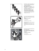
-
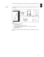
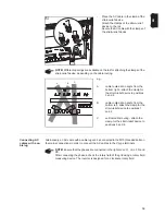
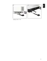
Place the AC cable in the clamp of the
strain-relief device
-
Attach the clamps of the strain-relief
device to the rail
-
Secure the AC cable with the clamps of
the strain-relief device
e.g.:
A
cable routed at an angle from the
bottom right - attach the clamp for
the strain-relief device to positions
3 and 4
B
cable routed at an angle from the
bottom left - attach the clamp for the
strain-relief device to positions 1
and 2
C
vertical cable routing - attach the
clamp for the strain-relief device to
positions 5 and 6
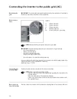
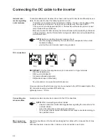
Connecting AC
cables with a ca-
ble lug
Alternatively, an AC cable with a cable lug can be connected to the M10 threaded bolts on
the mains connections in order to connect the AC cables to the V-type terminals.
5
NOTE!
Different openings are available on the rail for attaching the clamps of the
strain-relief device, depending on the cable routing.
1
A
B
C
2
4
6
3
5
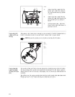
NOTE!
Ensure that the phases are connected in the right order: L1, L2, L3, N and
PE.
After connecting the phases, check the rotary field of the grid using a rotary field
measuring device. The inverter is designed for a clockwise rotary field.
Содержание Agilo 100.0-3
Страница 2: ...0...
Страница 4: ...2...
Страница 8: ...6...
Страница 13: ...General information...
Страница 14: ......
Страница 30: ...28...
Страница 31: ...Installation and commissioning...
Страница 32: ......
Страница 51: ...49 EN 1 2 Inserting the fuse grounds the solar modules on the negative pole 1 1 1 2 2...
Страница 53: ...51 EN 2 3 Tightening torque 3 Nm 1 3 2 4 5 4 3 2 4 5 1 5...
Страница 57: ...Operation...
Страница 58: ......
Страница 84: ...82...
Страница 85: ...Troubleshooting and maintenance...
Страница 86: ......
Страница 107: ...Appendix...
Страница 108: ......