


35
EN
Positioning the inverter
Prerequisites
Before positioning the inverter, clarify how the cables are going to be fed in.
If it is not going to be possible to feed any cables into the inverter once it has been posi-
tioned, all the AC, DC and data communication cables must, before the inverter is put in
place,
-
be dimensioned accordingly,
-
protrude at least 650 mm out of the floor.
Positioning the
inverter
IMPORTANT!
Ensure that any covers which were removed previously are refitted before
the inverter is moved to its final position (e.g. fit the rear base-cover before positioning the
inverter up against a wall).
Fixing material for fixing the inverter on the ground is not included with the inverter. The
installer is responsible for the proper selection of dowels, screws, etc..
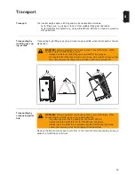
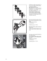
Transport the inverter to its location
Fit any covers that will no longer be accessible once the inverter is in its final position
Move the inverter into its final position
Adjust the inverter horizontally using the leveling feet.
The leveling feet are located at the bottom of the inverter, for better accessibility op-
tionally remove the left and right base-cover.
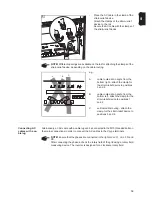
Depending on the accessibility fix the inverter with suitable dowels and screws ideally
4 x at the mounting lugs on the floor.
Notes regarding
the air supply
If the inverter is positioned in a protected area, the air supply to the inverter must be at least
1200 m³/h (approx. 20 m³/min).
WARNING!
Equipment that falls or topples over can cause serious or even fatal
injury.
-
Place the inverter on a solid, level surface in such a way that it remains sta-
ble.
-
Do not under any circumstances tip the inverter while it is being positioned.
CAUTION!
Risk of cable damage as a result of shearing or bending.
if any cables are protruding out of the floor, use a crane or forklift truck to lift the
inverter over the cables and position the inverter in its desired location.
WARNING!
Equipment that topples over can cause serious or even fatal injury.
-
Place the inverter on a solid, level surface in such a way that it remains sta-
ble.
-
Fix the inverter at the mounting lugs firmly to the ground.
1
2
3
4
5
Содержание Agilo 100.0-3
Страница 2: ...0...
Страница 4: ...2...
Страница 8: ...6...
Страница 13: ...General information...
Страница 14: ......
Страница 30: ...28...
Страница 31: ...Installation and commissioning...
Страница 32: ......
Страница 51: ...49 EN 1 2 Inserting the fuse grounds the solar modules on the negative pole 1 1 1 2 2...
Страница 53: ...51 EN 2 3 Tightening torque 3 Nm 1 3 2 4 5 4 3 2 4 5 1 5...
Страница 57: ...Operation...
Страница 58: ......
Страница 84: ...82...
Страница 85: ...Troubleshooting and maintenance...
Страница 86: ......
Страница 107: ...Appendix...
Страница 108: ......