


/ / FSP SERIES / / /
26
9.11 Pump Shaft Mounting and Alignment
9.11.1 Models FSPE and FSP...V
Note: After the IEC motor has been replaced the pump shaft
must be mounted and aligned.
Rotating Parts
Bruising and serious injuries.
Turn off the motor and prevent it from being able to be
turned on accidentally.
1. Take the key out of the motor shaft pin.
2. For electric motors with outputs higher than 22 kW:
Insert the supplied half-key.
3. Degrease the motor shaft pin and the drill hole on the pump
shaft using a cleaner, e.g., OKS 2610 Universal Cleaner.
4. Grind the motor shaft pin and the edges of the key slot with
grinding paper to eliminate unevenness and burrs.
5. Apply a sealing gel, e.g., Stucarit 309, to the motor shaft pin
in the region of the shaft shoulder.
6. Slide the pump shaft with the shrink ring onto the motor
shaft pin up to the shaft shoulder.
7. Tighten the screws crosswise on the shrink ring:
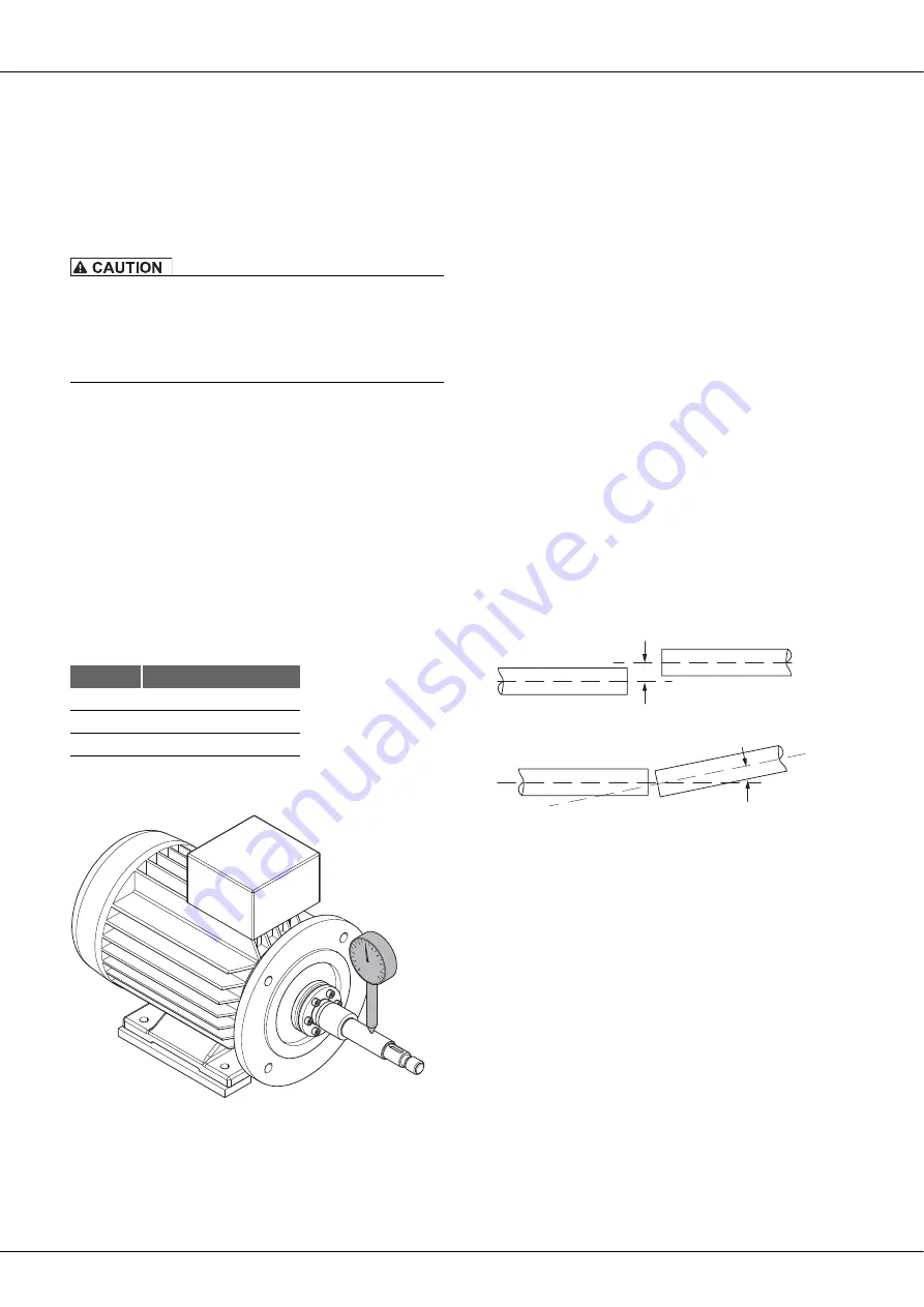
8. Attach the dial gauge onto the pump shaft to check the run-
out tolerance.
Fig. 47
Pump shaft runout tolerance measurement
9. Check the runout of the pump shaft as a function of motor
output.
– Motor < 30 kW: max. runout tolerance = 0.06 mm
– Motor > 30 kW: max. runout tolerance = 0.08 mm
10. Straighten the pump shaft if necessary.
9.12 Model L: Coupling Replacement
Only use couplings approved by
Fristam
. The coupling must be
appropriate for the characteristic curve of the pump. If you have
any questions, please contact
Fristam
.
Procedure
1. Turn off the motor and prevent it from being able to be
turned on accidentally.
2. Remove the coupling guard.
3. Detach the pump and the motor from the base frame or the
foundation and remove..
4. Turn off the coupling in accordance with the motor manu-
facturer's specifications.
5. Dispose of the old coupling parts in an environmentally
friendly manner.
6. Place new coupling parts (coupling tire, flanges, possibly
clamping rings) on the drive shaft and on the gear shaft.
7. Place the motor on the base frame or the foundation and
slightly tighten the fastening screws.
8. Check the parallel and angular misalignment of the shafts.
Fig. 48
Parallel misalignment
Fig. 49
Angular misalignment
9. Minimize deviations from the angular and parallel misalign-
ment. Realign the shafts if necessary.
10. Screw the motor to the base frame or the foundation.
11. For information on the spacing between the two coupling
flanges, please see the coupling installation manual. See
"Supplier Documentation“
in the attached documents.
12. Fasten the coupling flanges with the given spacing onto the
shaft.
13. Fasten the coupling tire. Tighten the screws uniformly and
crosswise. Heed the given tightening torques in the coupling
installation manual.
14. Mount the coupling guard.
Thread
Tightening Torque
M5
6 Nm
M6
12 Nm
M8
30 Nm
Содержание FSP Series
Страница 31: ...31 950 Spring Part Num ber Name ...