frio S1 Скачать руководство пользователя страница 16


16  |  © Frio 2021 - Rev. 0.3 - Updated 3/2/2021


4


I

NSTALLATION 

I

NSTRUCTIONS


NOTE: THE CONTROLLER MUST BE INSTALLED BY A LICENSED ELECTRICIAN OR QUALIFIED PROFESSIONAL IN 
ACCORDANCE WITH LOCAL AND NATIONAL ELECTRICAL CODES.  THE CONTROLLER MUST BE CONNECTED 

TO A CERTIFIED CIRCUIT BREAKER RATED FOR 30 A OR LESS.  NO OTHER TYPES OF DEVICES MAY BE PLACED ON THE 
CIRCUIT BREAKER. 

4.1


S

TEP 

1:


I

NITIAL 

I

NSPECTION AND 

P

LANNING


1.


Inspect the Frio S1 controller for any damage that may have occurred during shipping. 

2.


Layout and plan the heat tracing system, including all sensors, wiring, conduit, and junction boxes. 

3.


Determine the controller location.  The controller should be mounted on a fixed vertical surface.  The controller 
may be mounted outside but  should not be mounted in direct  sunlight to reduce  the chance of condensation 
forming in the controller. 

4.2


S

TEP 

2:


A

SSEMBLY AND 

M

OUNTING


1.


Once you have determined the wiring layout and conduit sizes, mark the 
bottom face of the controller for power and sensor connections.    If the 
controller is mounted outside, use only NEMA Type 4X (or higher) liquid-
tight conduit fittings and cable glands.   

2.


Drill holes on the bottom face of the controller (mount fittings inside of 
the  dashed  line  shown  in  Figure  1)  and  mount  your  conduit  and  cable 

fittings.  Do not drill holes within 0.5” of the edge 

of the enclosure.  After 

drilling the holes, ensure that all plastic shavings have been removed from 
the controller. 

3.


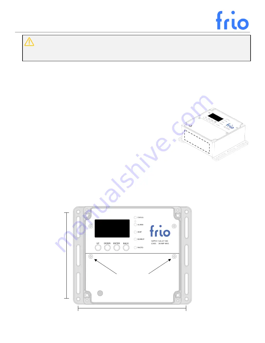
Mark  hole  locations  on  the  vertical  surface  where  you  will  mount  the  controller  according  to  the  dimensions 
shown in Figure 2.  Ensure the mounting surface is flat, permanent, and the controller is protected from damage.  

4.


Mount the controller to the vertical surface.   

Figure  1:  Frio  S1  controller  showing  the 
bottom side where to drill wiring holes. 

5.

60

 in

6.95 in. 

Screws to remove 

Wiring Cover 

Figure 2: Top View of the Frio S1 controller showing mounting hole dimensions. 

Содержание S1

Страница 1: ... Frio 2021 Rev 0 3 Updated 3 2 2021 S1 IoT Heat Trace Controller Operating Manual ...

Страница 2: ... Rev 0 3 Updated 3 2 2021 A B C D E F G 1 DEVICE DIAGRAM HMI Human Machine Interface A Screen B Buttons C LEDs D Device Reset Wiring Area E High Voltage Connections F Low Voltage Connections G Ethernet Connection ...

Страница 3: ...ure Maintenance 6 3 2 3 Manual Control 7 3 2 4 Cloud Control 7 3 3 Ground Fault Equipment Protection GFEP 7 3 3 1 GFEP Overview 7 3 3 2 Adjusting the GFEP Trip Level 8 3 3 3 Fire Protection Mode 8 3 3 4 Testing the GFEP circuit 8 3 4 Communication 8 3 4 1 S1 A Internet Connection 8 3 4 2 S1 C Cellular Internet Connection 10 3 4 3 BACnet 11 3 4 4 Dry Contact 12 3 5 Alarms 12 3 5 1 User settable Ala...

Страница 4: ...Start Up and Configuration 17 4 6 Step 6 Internet Connection BlinkUp 18 4 7 Step 7 Ground Fault Test 18 4 8 GFEP TEST FORM 19 5 Menus Navigation and Operation 20 5 1 LEDS 20 5 2 Main Screen 20 5 3 Main Menu 20 5 4 Settings 21 5 4 1 Advanced Settings 21 5 4 2 Alarm Settings 21 5 5 Start Up 22 5 6 Power Loss 22 5 7 Rebooting the Device 23 5 8 Clearing Device Settings 23 5 8 1 Restore Factory Default...

Страница 5: ... Frio cloud platform offers customizable SMS and email notifications so that the user can be alerted immediately if there are any issues with the system Users can access their S1 device remotely via the Frio cloud platform to check status activate the system or run a diagnostic test eliminating the need to physically check the heater control system If an internet connection is not available the S1...

Страница 6: ... from freezing In freeze protection mode the S1 will activate the heat trace circuit when the active temperature sensor reads a value below the temperature set point The S1 will then turn off the heat tracing circuit when the active temperature sensor reads a value above the temperature setpoint plus the dead band The dead band is used to prevent the system from turning on and off rapidly if the t...

Страница 7: ...from the cloud platform Alarms can be viewed via the cloud platform but must be cleared via the HMI on the physical device Users can control devices from the cloud platform by setting an override which will hold the device ON or OFF for a user specified period Overrides can be set for a maximum of 21 days If a device loses power during the override period then subsequently regains power the overri...

Страница 8: ...the GFEP circuit follow the step by step instructions in section 4 7 of this manual Periodic testing of the GFEP circuit is required in most settings The results of the test are to be recorded on a test form such as the one provided with the S1 Installation Instructions in Section 4 The tester shall record on the form the date the test was performed and the results and shall ensure the form is ret...

Страница 9: ...a rogue Wi Fi access point masquerading as your network router It can do this by transmitting the same SSID as your network but at a higher signal strength but without the password which the assailant does not know The Frio S1 A does not currently support enterprise level Wi Fi authentication 802 1x which requires that you log in with a username and password as well as the customary SSID An end us...

Страница 10: ...Repeat Connecting to server 500ms 500ms 500ms 250ms Repeat Connected to server 500ms 500ms Repeat Proxy address or port incorrect 500ms 500ms 250ms 250ms 250ms 250ms Repeat Proxy credentials rejected 500ms 500ms 250ms 250ms 250ms 250ms 250ms Device lost connection 500ms 500ms Repeat Device deliberately offline 500ms 250ms 250ms 250ms Repeat Updating Firmware Continuous for duration of update Norma...

Страница 11: ...ms 500ms Repeat Device deliberately offline 500ms 250ms 250ms 250ms Repeat Updating Firmware Continuous for duration of update Normal operation LED not illuminated 3 4 3 BACnet The following table includes the BACnet Points List that will be available on future firmware versions The points list is included to aid in the design of systems that will communicate with the Frio S1 via BACnet For the la...

Страница 12: ...olved at the device via the HMI A summary of the available alarms is shown in the table below Alarm Type Critical Default Threshold Range Increment Delay Default Delay Low Current User Settable No 0 A 0 30 A 0 1 A 0 500 s 5 s High Current User Settable Yes Shuts Off 30 A 0 30 A 0 1 A 0 500 s 300 s Low Temperature User Settable No 35 F 0 300 F 1 F 0 500 s 300 s High Temperature User Settable No 140...

Страница 13: ...atching and must be cleared via the HMI 3 5 4 Active Alarms Active alarms can be viewed from the HMI by selecting Active Alarms from the Main Menu The active alarm page on will display all active alarms The user may select an alarm to view Duration the time since the alarm condition started Returned whether the alarm condition ceased returned to normal To reset the alarms select Active Alarms from...

Страница 14: ...ase Double pole relay is safe for 240 VAC with two hot legs Maximum Load 30 A resistive Wire size 10 18 AWG GFEP Programable from 30 mA to 300 mA default 30 mA Manual and automatic test Fire protection mode allows user to disable GFEP Sensor Inputs Frio Thermistor 2 Wire shielded pair 24 AWG leads 10k NTC thermistor with 1 accuracy operating range of 40 C to 105 C leads and thermistor tip are blac...

Страница 15: ...nditions 1 This device may not cause harmful interference and 2 this device must accept any interference received including interference that may cause undesired operation NOTE THE S1 A AND S1 C HAVE BEEN TESTED AND FOUND TO COMPLY WITH THE LIMITS FOR A CLASS A DIGITAL DEVICE PURSUANT TO PART 15 OF THE FCC RULES THESE LIMITS ARE DESIGNED TO PROVIDE REASONABLE PROTECTION AGAINST HARMFUL INTERFERENC...

Страница 16: ...SSEMBLY AND MOUNTING 1 Once you have determined the wiring layout and conduit sizes mark the bottom face of the controller for power and sensor connections If the controller is mounted outside use only NEMA Type 4X or higher liquid tight conduit fittings and cable glands 2 Drill holes on the bottom face of the controller mount fittings inside of the dashed line shown in Figure 1 and mount your con...

Страница 17: ...ound sheath of the heat trace must be connected to the ground terminal on the controller 4 Connect the power leads as shown in Figure 3 The ground connection on the controller must be properly connected to ground in accordance with local and national electrical codes 5 All power connections and wires should be installed in accordance with all local and national electrical codes Use crimp connected...

Страница 18: ...n Menu 2 Select GFEP Test and press enter 3 You will be prompted to Test GFEP now to test the GFEP circuit select Yes 4 The controller will display RUNNING GFEP TEST during the test and TEST SUCCESS for a successful test If the test is not successful the device will display TEST FAILED If the GFEP test fails turn off the system at the breaker and disconnect the heat trace Rerun the test with nothi...

Страница 19: ...2 2021 4 8 GFEP TEST FORM DATE GFEP TEST RESULT TEST PERFORMED BY COMPANY NOTE THIS TEST FORM MUST BE RETAINED BY THOSE IN CHARGE OF THE BUILDING S ELECTRICAL INSTALLATION IN ORDER TO BE AVAILABLE TO THE AUTHORITY HAVING JURISDICTION ...

Страница 20: ...r BlinkUp process only ensure phone screen covers this area during BlinkUp 5 2 MAIN SCREEN The main screen displays information about the device at all times including Current Displays the current draw of the heating system Temperature Displays the temperature of the control temperature sensor Connected Provides connection status Yes or No 5 3 MAIN MENU Press any button to enter the Main Menu and ...

Страница 21: ...PROTECTION MODE DISABLES THE GFEP TRIP CIRCUIT THIS CONFIGURATION IS NOT RECCOMENDED AND MUST BE USED IN CONJUNCTION WITH THE DRY CONTACT ALARM SIGNAL TO ALERT THE SYSTEM OPERATOR TO A GROUND FAULT CONDITION Network Settings Adjust Network Settings Rerun BlinkUp Reruns the BlinkUp process to provision the device YES NO Turn of Networking Disables device networking YES NO Clear Network Credentials ...

Страница 22: ...eady to use If the device has never been connected to a network or if the network credentials have been cleared the BlinkUp LED will flash orange after power on While the BlinkUp LED is flashing orange you may BlinkUp the device using the Frio mobile App To initiate BlinkUp after the device has finished startup i e after the BlinkUp LED has turned off select Settings from the Main Menu then select...

Страница 23: ...8 1 Restore Factory Default Settings To restore the factory default settings select Settings from the Main Menu then select Advanced Settings from the Settings Menu Select Restore Default Settings from the Advanced Settings Menu You will be asked if you want to Reset and Reboot Select Yes to reset the device to the factory default settings 5 8 2 Clear Network Credentials To clear the Wi Fi credent...

Страница 24: ...version is retained on the device If the update fails or the device is disconnected during the update the previous firmware version will be reloaded until the device is able to retry the update at a later time When an update occurs the device will restart shutting off the heating system if it is on Once the update is complete the device will resume normal operation Updates typically take less than...

Отзывы: