background image

3

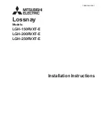
DAMPER/DUCT CONNECTOR (F30WV HOOD ONLY)

HINGE
PINS

DUCT
KNOCKOUTS

PREPARE THE HOOD

1. Unpack hood and check contents. You should receive:

1 -Aluminum Filter (F30WV hood only)
1 -3-1/4" x 10" Damper/Duct Connector (mounted

inside of hood for shipping only) (F30WV
hood only)

1 - Ductree filter (F24WR and F30WR hoods  only)

2. Remove wiring box cover. Under cover find:

1 -Plastic Bag containing loose mounting hard-

ware

3. Remove top or rear electrical knockout. (FIG. 2)

4. (F30WV hood 

ONLY

) Remove duct knockout. Insert screw-

driver under edge of knockout, break tabs, and peel knock-
out back with pliers. (FIG. 3)

5. (F30WV hood 

ONLY

) Install damper/duct connector over

opening made in STEP 4. Use #8B sheet metal screws pro-
vided. (FIG. 3)

FIG. 1

FIG. 2

   FIG. 3

FIG. 4

WIRING BOX COVER

DUCTFREE
FILTER
(F24WR &
F30WR
HOOD
ONLY)

ALUMINUM
FILTER
(F30WV
HOOD
ONLY)

KEYHOLE

SLOTS

PREPARE THE
INSTALLATION LOCATION

Omit STEP 1 if hood will be installed under cabinets with flush
bottom.

1. (For installation on recessed bottom cabinets only) Attach a

wood filler strip at each side of recessed area under cabi-
net. Use two 1" x  2" strips cut to length. If recess is deeper
than 1" use thicker strips. Attach strips with 1-1/4" wood
screws, 3" from each end of strip. See FIG. 4.

2. Measure and mark the following (FIGS. 5A & 5B):

a.) Electrical wiring opening in wall or cabinet.

b.) Duct opening in wall or cabinet (F30WV hood  

ONLY

).

WARNING

WHEN CUTTING OR DRILLING INTO WALL OR CABINET,
BE CAREFUL NOT TO CUT EXISTING ELECTRICAL
WIRING.

3. Use 1-1/4" bit to drill opening for electric wiring.

4. Cut out duct opening in wall or cabinet with saber saw or

keyhole saw.

5. Center hood in installation opening and trace keyhole slots

onto wood filler strips on cabinet bottom.

6. Screw four #10 x 7/8 wood screws into exact center of narrow

end of traced keyhole slots. Allow 3/8" of screws to project, so
that hood can be fitted into place later.

ELECTRICAL
KNOCKOUTS

Содержание F30WR01E

Страница 1: ...unattended at high settings Boilovers cause smoking and greasy spillovers that may ig nite Heat oils slowly on low or medium settings 2 Always turn hood ON when cooking at high heat or when cooking flaming foods 3 Clean ventilating fans frequently Grease should not be al lowed to accumulate on fan or filter 4 Use proper pan size Always use cookware appropriate for the size of the surface element F...

Страница 2: ... duct run and a minimum number of elbows There are several choices shown FIGS A F below FIG A Ducting directly through the wall for range hoods mounted on an exterior wall Shown are two ways to duct through an outside wall If a wall cap is used directly off the back of the hood special care must be taken to make sure that the damper in the damper duct connector on the hood and damper in the wall c...

Страница 3: ...THE INSTALLATION LOCATION Omit STEP 1 if hood will be installed under cabinets with flush bottom 1 For installation on recessed bottom cabinets only Attach a wood filler strip at each side of recessed area under cabi net Use two 1 x 2 strips cut to length If recess is deeper than 1 use thicker strips Attach strips with 1 1 4 wood screws 3 from each end of strip See FIG 4 2 Measure and mark the fol...

Страница 4: ...R LINE FILLER STRIPS WALL CAP CABINET ROOF CAP DUCT SOFFIT CABINET INSTALL THE DUCTWORK This section for F30WV hoods only F24WR and F30WR hoods skip this section and go on to Install Range Hood NOTE These instructions will follow plans made on Page 2 Start at the exterior and run ductwork back to the range hood For best possible performance use the shortest possible duct run and a minimum number o...

Страница 5: ...Flaming grease can also be extinguished with baking soda or a multi purpose dry chemical extinguisher Turn off surface units if you can do so without getting burned FIG 10 FIG 11 FIG 12 FIG 13 BLACK WIRES GREEN GROUND SCREW GROUND WIRE BARE OR GREEN WIRE GROUNDING BRACKET STAR LOCKNUT WHITE WIRES FIG 9 USE AND CARE SWITCHES The fan and light are each controlled by a rocker switch The light switch ...

Страница 6: ...Includes Key Nos 6 7 8 10 Aluminum Filter 11 Filter Retainer 12 8B x 1 4 Hex Head Sheet Metal Screws 2 Required 13 Damper Flap 14 Damper Bushing 15 Damper Assembly Includes Key Nos 13 14 and 21 16 Nameplate Black Nameplate White 17 2 Speed Motor Switch Black 2 Speed Motor Switch White 18 Light Switch Black Light Switch White 19 Motor Receptacle with Wires 20 10 32 x 1 2 Green Ground Screw 21 Dampe...

Страница 7: ...ing Bracket 9 Motor Assembly Includes Key Nos 6 7 8 10 Ductfree Filter 11 Filter Retainer 12 Nameplate Black Nameplate White Nameplate Bisque 13 2 Speed Motor Switch Black 2 Speed Motor Switch White 2 Speed Motor Switch Bisque 14 Light Switch Black Light Switch White Light Switch Bisque 15 Motor Receptacle with Wires 16 10 32 x 1 2 Green Ground Screw 17 Grommet Light Bulb 75 Watt not included Orde...

Страница 8: ...RCHANTABILITY OR FITNESS FOR A PARTICULAR PURPOSE ARE LIMITED TO ONE YEAR OR THE SHORTEST PERIOD ALLOWED BY LAW BUT NOT LESS THAN ONE YEAR ELECTROLUX SHALL NOT BE LIABLE FOR CONSEQUENTIAL OR INCIDENTAL DAMAGES SUCH AS PROPERTY DAMAGE AND INCIDENTAL EXPENSES RESULTING FROM ANY BREACH OF THIS WRITTEN LIMITED WARRANTY OR ANY IMPLIED WARRANTY SOME STATES AND PROVINCES DO NOT ALLOW THE EXCLUSION OR LIM...

Отзывы: