11
920-075-09
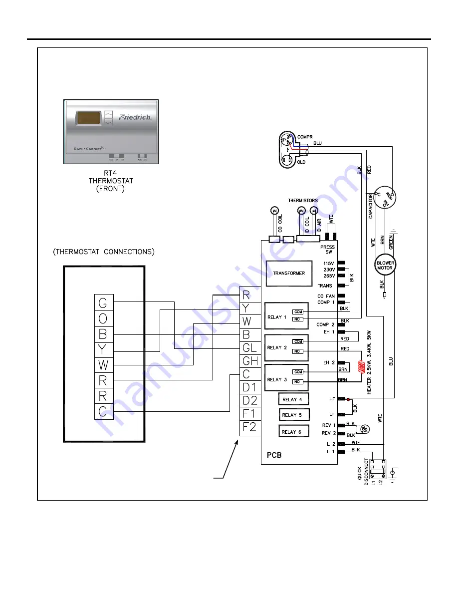
NOTE:
THE DIAGRAM ABOVE ILLUSTRATES THE TYPICAL THERMOSTAT WIRING. SEE THE UNIT
CONTROL PANEL FOR THE ACTUAL UNIT WIRING DIAGRAM AND SCHEMATIC.
CONNECTION TERMINAL
Electrical & Thermostat Wiring Diagrams
Figure 8
Страница 1: ...920 075 09 11 07 VERT I PAK A SERIES SINGLE PACKAGE VERTICAL AIR CONDITIONINGSYSTEM 9 000 18 000 BTU h INSTALLATION OPERATION GUIDE...
Страница 2: ...d Thermostat Wiring Diagrams 11 Chassis Operation Fresh Air Door 12 Low Ambient Protection 12 Room Freeze Protection 12 Emergency Heat Override 12 Emergency Heat Operation 12 Service Servicing Chassis...
Страница 3: ...louver should be maintained For major obstructions such as a solid fence wall or other heat rejecting device like a condensing unit a mini mum distance of 72 should be kept 12 24 60 VPAK VPAK VPAK POL...
Страница 4: ...1Ph 60Hz NOMINAL CAPACITY A Series Btu h 09 9 000 12 12 000 DESIGN SERIES A 32 47 Cabinet SERIES V Vertical Series 18 18 000 24 24 000 E Cooling with electric heat H Heat Pump Refer to electrical dat...
Страница 5: ...ge 7 for wire size Use HACR type breakers to avoid nuisance trips All field wiring must be done in accordance with NEC and local codes Sample Nameplate MODEL NO 1 SERIAL NO FRIEDRICH AIR CONDITIONING...
Страница 6: ...ions 24 5 8 wide x 30 7 8 high VPRG4 Access Panel cutout dimensions 27 wide by 55 3 4 high See Figure 8 Page 10 for proper chassis installation Figure 3 Typical Utility Closet Chassis Shown in Closet...
Страница 7: ...ide wall plenum Part A Inside Wall Plenum Part B Wall Plenum Outdoor Louver Installation Rough opening dimension 24 5 8 wide x 30 7 8 high Ensure that the bottom of the plenum is 1 1 2 from the floor...
Страница 8: ...first stage increases energy efficiency utilizing a factory installed fan that slings the cold condensate onto the hot outdoor coil Part 2 When high outdoor humidity prevents the slinger from disposin...
Страница 9: ...talled in accordance with the VPAWP1 8 1 14 Installation Manual B Place the chassis into the closet with the outdoor side facing the wall plenum opening C Slide the chassis into the wall plenum until...
Страница 10: ...ol box and under the control components in the box to reach the connection terminal for the wiring 4 Make the wire connections appropriately matching the wires as the shown in the wiring diagram 5 Onc...
Страница 11: ...09 NOTE THE DIAGRAM ABOVE ILLUSTRATES THE TYPICAL THERMOSTAT WIRING SEE THE UNIT CONTROL PANEL FOR THE ACTUAL UNIT WIRING DIAGRAM AND SCHEMATIC CONNECTION TERMINAL Electrical Thermostat Wiring Diagram...
Страница 12: ...sh Air Door is an intake system The fresh air door is opened via a slide on the front of the chassis located just above the indoor coil Move the slide left to open and right to close the fresh air doo...
Страница 13: ...f your Vert I Pak and allows lint and dirt to accumulate on the indoor air coil Lint and dirt on the indoor air coil can damage your unit and void the warranty The air filter should be replaced as it...
Страница 14: ...coil Fan motor failure Restricted air flow Non condensables in refrigeration system 07 I D coil temperature 30 Deg F for 2 consecutive minutes Alternately flash set point and error code Continue fan o...
Страница 15: ...pecial color to match the exterior wall ARCHITECTURAL LOUVER Extruded aluminum louver that attaches to the outdoor section of the wall plenum DIMENSIONS 31 1 16 high x 25 9 16 wide Same as VPAWP1 8 bu...
Страница 16: ...n contact the Friedrich Air Conditioning Company International Division Any defective part to be replaced must be made available to FRIEDRICH in exchange for the replacement part Reasonable proof must...