


11
920-198-00
CHECK FILTER
– When the
fi
lter needs to be checked, an icon
CHECK
FILTER
appears on screen. The word “
RESET
” appears next to the
BACK
button.
The
CHECK
FILTER
alert is issued when the fan run time is greater than 500 hours.
This alert may be reset by the user (Refer to Special Functions, Filter Reset).
Maintenance Required
– When maintenance is required, a service icon
appears on screen. This icon will not be dismissed until maintenance
has been performed. If the service icon
fl
ashes, maintenance is
required and must only be performed by quali
fi
ed service personnel. When
the icon
is on standby the system has sensed an abnormal condition.
For example: The air in/out louvres may be blocked. Once proper air
fl
ow
is established the service icon
goes away.
Wait
– The WAIT icon illuminates when the compressor lockout is active.
Whenever the compressor shuts off, system pressures must be allowed
to equalize. At this time, an internal timer begins a count-down from up to
240 seconds. If a demand for heat or cool occurs during this count-down
the WAIT icon
displays letting you know that the compressor will not
operate until the count-down has completed. This timer prevents damage
to the unit if it tries to start too quickly after it stops running. Normally the
WAIT icon is off. Once the timer has cleared, the air conditioner will
heat or cool based on the temperature setting. Electric heat is not affected
by this timer.
Protection Alert (Freeze)
– If the room freeze protection is active, the
display indicates this by showing Room Freeze Protection "FRZ". Once
the condition is satis
fi
ed, the “FRZ” display is removed. If the room
temperature is less than 40° F (4° C), and the air conditioner is equipped with
electric heat, the room freeze protection will activate. The air conditioner
will run high fan and electric heat until the room temperature reaches
46° F (8° C). Pressing the
BACK
button delays the freeze protection function
for
fi
ve (5) minutes.
Low Battery
– When the battery is low a warning display
will be
inserted before other messages such as “COOL”. If the Low Battery
alert is on, the battery in the control unit must be changed. Refer
to the changing the battery procedure. Once the battery is changed, the
alert message will go off. Refer to Troubleshooting Tips. Under normal
conditions the battery life should be greater than 7 years.
Special Functions
Panel Lock
– The front panel push buttons can be locked to prevent
inadvertent operation. To lock the front panel, press and hold the
SCHEDULE
+
DISPLAY
ENTER
buttons for three (3) seconds. A double beep indicates your mode
change was successful and a icon appears on the display. To unlock
the display, press and hold the
SCHEDULE
+
DISPLAY
ENTER
buttons for three (3) seconds.
The icon will no longer be visible.
Filter Reset
– If the
CHECK
FILTER
icon displays, the timer may be reset by pressing
and holding the
BACK
button for three (3) seconds. A beep indicates the
CHECK
FILTER
system timer was reset and the
CHECK
FILTER
icon and the word "
RESET
" will
no longer be visible.
User Menu Functions
– The User Menu Functions allows you to change
the following selections: Set TIME, 12/24 Hour Clock Format, BEEP ON /
OFF, DIM ON / OFF, Emergency Heat (EMHT) ON / OFF, Auto BAND Adjust,
F/ C Select, FRZ ON / OFF and Temp Offset.
To enter the User Menu, press and hold
DISPLAY
ENTER
for 3 seconds, the TIME
selection appears. Use the
(UP) or
(DOWN) buttons to scroll
through the User Menu. Press the
DISPLAY
ENTER
button to enter the displayed
function. If left inactive for 15 seconds the User Menu display will no longer
be visible and it returns to normal operation mode display. To manually
exit the User Menu, press the
BACK
button.
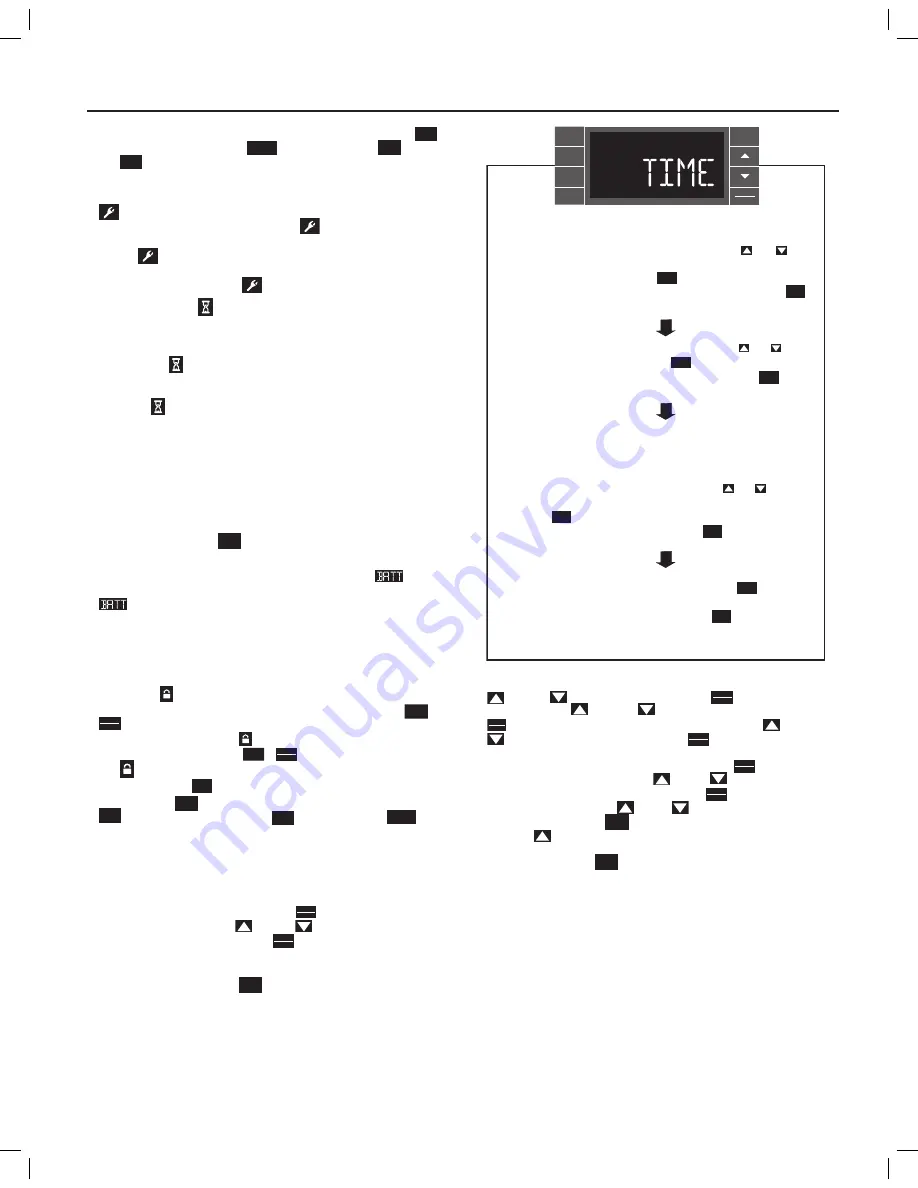
Time Setting
– When in the User Menu, on the Control Panel, use the
(UP) and
(DOWN) to select TIME. Push
DISPLAY
ENTER
, the hours segment
fl
ashes. Use the
(UP) and
(DOWN) to set the hour, then push
DISPLAY
ENTER
. The minutes segment and AM or PM
fl
ashes. Use the
(UP) and
(DOWN) to set the minutes, then push
DISPLAY
ENTER
.
NOTE:
If the AM or PM indicator is incorrect, push
DISPLAY
ENTER
until the hours
segment
fl
ashes, use the
(UP) or
(DOWN) to advance
the hour segment 12 hours, then push
DISPLAY
ENTER
. The day of the week
displays. Use the
(UP) or
(DOWN) to select the current
day. Press the
BACK
key to go back to the TIME screen. Press
(UP) to go to the next menu 1224.
NOTE:
Pressing
the
BACK
button again will exit the user menu function
mode. Or simply leave the control inactive for 15 seconds and
the control will return back to normal operation.
FRR062
The hour digits flash first. The user presses the or
to change the hours. To change AM-PM, the hours must be
advanced 12 hours. Press the key to change to the
minutes. To exit the selection process, user presses the
key which will go to the time screen.
The minutes digits flash. The user presses the or
to change the minutes. Press the key to change the days.
To exit the selection process, the user presses the key
which will go to the time screen.
The dot underneath the days of the week begins to blink to
indicate which day it is. If the user has not set the date before
the dot starts on Monday. If the user is making a correction to
previously set information the dot appears under whichever
day the unit thinks it is. The user can press or to move
the dot left or right (respectively) along the week. The user
presses to loop back to the hours setting. To exit the
selection process, the user presses the key which will go
to the time screen.
Tuesday has been selected. The user presses to loop
back to the hours setting. To exit the selection process and
accept the changes, the user presses the key which will go
to the time screen.
DISPLAY
ENTER
DISPLAY
ENTER
BACK
BACK
DISPLAY
ENTER
DISPLAY
ENTER
BACK
BACK
SYSTEM
FAN
MODE
FAN
SPEED
SCHEDULE
BACK
DISPLAY
ENTER
EXIT


