background image

13

920-087-04

A. Electrical Rating Tables

All 230/208 volt units are equipped with power cords. See Appendix A on page 21 for wiring in struc tions on 265V units.

NOTE:  Use Copper Conductors ONLY.  Wire sizes are per NEC, check local codes for over seas ap pli ca tions.

WIRE SIZE

Use ONLY wiring size recommended for 
single outlet branch circuit.

FUSE/CIRCUIT 
BREAKER

Use ONLY type and size fuse or HACR cir-
cuit breaker indicated on unit’s rating plate. 
Proper current protection to the unit is the 
responsibility of the owner. NOTE: A time 
delay fuse is provided with 265V units.

GROUNDING

Unit MUST be grounded from branch circuit 
through service cord to unit, or through sep-
arate ground wire provided on permanently 
connected units. Be sure that branch circuit 
or general purpose outlet is grounded. The 
fi eld supplied outlet must match plug on 
service cord and be within reach of service 
cord. Refer to Table 1 for proper receptacle 
and fuse type. Do NOT alter the service cord 
or plug. Do NOT use an extension cord.

RECEPTACLE

The fi eld supplied outlet must match plug on 
service cord and be within reach of service 
cord. Refer to Table 1 for proper receptacle 
and fuse type. Do NOT alter the service cord 
or plug. Do NOT use an extension cord.

WIRE SIZING

Use recommended wire size given in Table 
2 and install a single branch circuit. All wiring 
must comply with local and national codes. 
NOTE: Use copper conductors only.

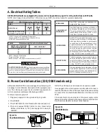
B. Power Cord Information (230/208V models only)

All Friedrich 230/208V PTAC units are shipped from the factory with 
a Leakage Current Detection Interrupter (LCDI) equipped power 
cord. The LCDI device meets the UL and NEC requirements for 
cord connected air conditioners effective August 2004.

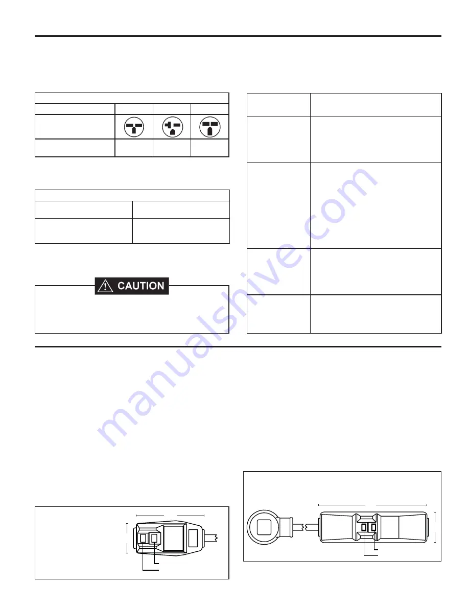
To test your power supply cord:

1.  Plug power supply cord into a grounded 3 prong outlet.

2.  Press RESET.

3.  Press TEST (listen for click; Reset button trips and pops out).

4. Press and release RESET (listen for click; Reset button 

latches and remains in). The power supply cord is ready for 
operation.

ELECTRIC SHOCK HAZARD!

  Turn off electric power before service or installation. 

All electrical connections and wiring MUST be installed by a qualifi ed electrician and 

conform to the National Electrical Code and all local codes which have jurisdiction. 

Failure to do so can result in property damage, personal injury and/or death.

   HACR – Heating, Air Conditioning, Refrigeration

*   May be used for 15 Amp applications if fused for 15 Amp

   NOTE: 265 volt units are hard wired.

Table 1                250 V Re cep ta cles and Fuse Types

AMPS

15

20*

30

RECEPTACLE

TIME-DELAY TYPE FUSE
(or HACR circuit breaker)

15

20

30

   AWG – American Wire Gauge 

*   Single circuit from main box
** Based on copper wire, single in su lat ed conductor at 60°C

Table 2               Recommended branch circuit wire sizes*

NAMEPLATE / MAXIMUM 

CIRCUIT BREAKER SIZE

AWG  WIRE SIZE**

15
20
30

14
12
10

NOTE: The LCDI device is not intended to be used as a switch.

Once plugged in the unit will operate normally without the need to 
reset the LCDI device. If the LCDI device trips and requires resetting 
the cause of the trip should be identifi ed prior to further use of the 
PTAC.

If the device fails to trip when tested or if the power supply cord is 
damaged it must be replaced with a new supply cord obtained from 
the product manufacturer, and must not be repaired.

Figure 10b

30A LCDI Device

15/20A LCDI Device

Figure 10a

TEST

RESET

Test Button

Reset Button

2"

4.1"

Test Button

Reset Button

7"

2"

Содержание HEAT PUMPS

Страница 1: ...920 087 04 10 06 PTAC PACKAGED TERMINAL AIR CONDITIONERS HEAT PUMPS Standard Control Remote Thermostat Seacoast Protected INSTALLATION OPERATION GUIDE ...

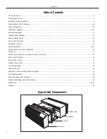
Страница 2: ...nstallation 14 15 Digital Control User Input Configuration 16 Operation 17 Remote Thermostat and Low Voltage Control Connections 18 Desk Control Terminals 19 Auxiliary Fan Control 19 Fresh Air Vent Control 19 Air Discharge Grille 19 Start up Checklist 20 Appendix A Electrical Wiring for 265 V Models 21 Routine Maintenance 22 Basic Troubleshooting Techniques 23 Digital Control Diagnostics and Test ...

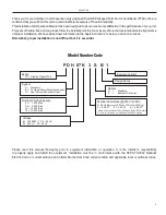
Страница 3: ...r to equipment installation or operation It is the installer s responsibility to properly apply and install the equipment Installation must be in conformance with the NFPA 70 2002 National Electric Code or current edition and Uniform Mechanical Code current edition and applicable local or national codes Model Number Code PD H 07 K 3 S B 1 Engineering Digit Design Series Options S Standard C Seacoa...

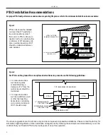
Страница 4: ...TAC units should be installed no closer than 12 apart when two units are side by side If three or more PTAC units are to operate next to one another allow a minimum of 36 between units Also a vertical clearance of 60 should be maintained between units installed Figure1 BETWEEN PTACs THREE OR MORE PTACs BUILDING ELEVATION ADJACENT 36 MINIMUM 6 MINIMUM FROM GRADE GROUND FLOOR PTACs TWO ADJACENT PTAC...

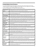
Страница 5: ...iedrich digital PTAC features a self diagnostic program that can alert maintenance to component failures or operating problems The internal diagnostic program saves properties valuable time when diagnosing running problems ServiceErrorCode Storage The self diagnosis program will also store error codes in memory if certain conditions occur and correct themselves such as ex treme high or low operati...

Страница 6: ... is diabled and the fan continues to operate based on demand Once the coil temperature returns to 45 F the compressor returns to operation Ultra QuietAirSystem The new Friedrich PD series units feature a indoor fan system design that reduces sound levels without lowering airflow and preventing proper air circulation HighEfficiency The Friedrich PTAC benefits quality components and extensive develo...

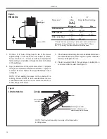
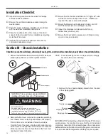
Страница 7: ...nylhose obtained locally toconnecttheinternaldraintubetothedrainsystem in the building 6 Referring to Detail A on page 6 locate and assemble the 2 two cover plates and gaskets over the drain holes at the rear of the wall sleeve Attach them with the 10 sheet metal screws provided Make certain that the four overflow slots at the rear of the wall sleeve are not blocked See drawing of the back of the ...

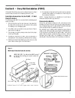
Страница 8: ... plate with the flange toward the wall sleeve 3 Attach the drain tube assembly to one of the two drain holes at the rear of the wall sleeve The large flange on the mounting plate is positioned at the bottom of the sleeve facing toward the sleeve Detail B When the drain tube is positioned at the desired angle tighten the screws NOTE If the wall sleeve has not been installed the drain tube must be r...

Страница 9: ...ds the outside to facilitate condensate drainage It should be level side to side and the front should be 1 4 bubble higher than the back DO NOT allow any pitch toward the inside Electrical shock hazard Turn electric power OFF at the fuse box or service panel before making any electrical connections and ensure a proper ground connection is made before connecting line voltage Failure to do so can re...

Страница 10: ...truct wall opening to comply with all applicable building codes Main studs Jack studs Main studs Jack studs Lintel Mounting screw holes No holes in bottom of wall sleeve unless drain kit is used 5 If the chassis and exterior grille are to be installed later leave the weatherboard and center support in place otherwise remove and dispose of them 6 Provide a support lintel if the wall sleeve is insta...

Страница 11: ...Improper fabrication or installation of a wall sleeve extension will impair PTAC performance Extension Installation Secure the wall sleeve extension to the wall sleeve before installing it in the wall Refer to Figure 8 for a guide for fabrication ofacondensatedrippanel ThepanelMUSTextendthefulldepth of the wall sleeve and the wall sleeve extension Pay particular care in sealing and caulking the pa...

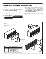
Страница 12: ...ched to the grille and an anchor point inside the building during installation Installation Instructions Model PXGA Standard Grille 5 Grasp the grille by the attached plastic handles Position it with the condensate drain knockouts facing down From inside the building maneuver the grille through the wall sleeve and pull toward you until the screw heads are inserted into the keyhole slots at the top...

Страница 13: ...I device meets the UL and NEC requirements for cord connected air conditioners effective August 2004 To test your power supply cord 1 Plug power supply cord into a grounded 3 prong outlet 2 Press RESET 3 Press TEST listen for click Reset button trips and pops out 4 Press and release RESET listen for click Reset button latches and remains in The power supply cord is ready for operation ELECTRICSHOC...

Страница 14: ...r Chassis shipping bracket Shipping pallet IMPORTANT When installing a Friedrich P Series PTAC into an existing sleeve it is important to ensure that the unit is installed completely Inspection of the air seal between the condenser air baffles and around the indoor mounting flange is recommended In some cases additional gaskets or baffling may be required Wall sleeve Weatherboard Center support 1 ...

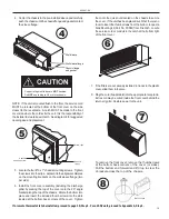
Страница 15: ...the screws into the clips adjacent to the alignment dimples on the mounting brackets on the wall sleeve flange two per side 6 Install the front cover assembly including the discharge grille by placing the top of the cover onto the 90 angle bracket along the top of the chassis Rotate the bottom into place and insert the included thumb screws into the slots located at the bottom back corners of the ...

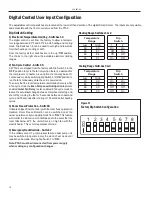
Страница 16: ...de the Even Temp Load Anticipation feature is enabled Quiet Fan Delay is also enabled in fan cycle mode to lessen the acoustical change between compressor start up and shut off by running the fan for 5 seconds before each demand cycle and 30 seconds after cooling or 15 seconds after heating cycles 3 Room Freeze Protection Switch 6 Unitsareshippedfromthefactorywiththeroomfreezeprotection disabled R...

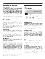
Страница 17: ... a heat pump to maintain the room temperature while running more efficiently than resistance heat only models If the room temperature should fall more than 5 F from the set temperature the unit will run the resistance heater The fan operation is dependent on the fan mode selected either continuous or cycling Dip switch 5 controls the fan mode see page 16 for setting Whentheoutdoorcoiltemperaturefa...

Страница 18: ...theSmartCentercontroloftheunitreplace the jumper wire between the GL and GH terminals that was removed in step 1 ThermostatConnections C Common Ground W Call for Heating Y Call for Cooling R 24V Power from Unit GL Call for Low Fan GH Call for High Fan B Reversing Valve Energized in heating mode PDH Models Only If only one G terminal is present on thermostat connect to GL for low fan or to GH for h...

Страница 19: ...and or tampering with the unit s internal wiring can void the equipmentwarrantyandmayresultinpropertydamage personal injury or death Other manufacturer s PTACs and even older Friedrich models may have different control wire connections Questions concerning proper connections to the unit should be directed to the factory Wire Size Maximum Length 24 400 ft 22 600 ft 20 900 ft 18 1500 ft 16 2000 ft D...

Страница 20: ...ecure components and accessories such as the control door and front cover Check the unit air filter condenser coil and evaporator coil for any obstructions Check for proper operation of all components Instruct the owner or operator of the units operation and the manufacturer s recommended routine maintenance schedule NOTE It is highly recommended that a maintenance schedule log book be prepared fo...

Страница 21: ...oved for ease of maintenance and service to the chassis Line Voltage Connections Figure15 5 Make the appropriate electrical connections within the control box then secure the box on the chassis Detailed instructions are included with the installation instructions for the conduit kit PXCJ 6 Route the line voltage power conduit from the control box straight down the right front to the bottom side of...

Страница 22: ... sleeve NOTE Do not use a caustic coil cleaning agent on coils or base pan Use a biodegradable cleaning agent and degreaser NOTE Units are to be inspected and serviced by qualified service personnel only Discharge Air Grille Filters Return Air Grille Front Cover Evaporator Coil Indoor Blower Housing Gasket Condenser Shroud Condenser Fan Blade Indoor Blower Innerwall Basepan Outdoor Grille Wall Sle...

Страница 23: ...ngineer for proper sizing Istheoutdoortemperature60 Forbelow The unit is designed for outdoor temperatures above 60 F Istheindoortemperature80 Forabove Ambient indoor temperatures of 80 F or above will take a longer period of run time to cool down the area Long run times may indicate that the unit is undersized Isindoorhumidityhigh This condition will cause the unit to operate longer to remove hum...

Страница 24: ...lash set point and error code Automatically change over to Electric heat Mode only Leave unit running Defective sensor 06 If O D coil Temperature 175 Deg F for 2 consecutive minutes Heat Pump models only Alternate flash set point and error code Shut unit down for 5 minutes then try again 2 times if fails the 3rd time then shut down unit Dirty coil Fan motor failure Restricted air flow Non condensa...

Страница 25: ...s to the outside of the wall sleeve when the wall is greater than 11 inches thick 9 when a subbase is used 10 inches when a lateral duct is used Up to three exten sions my be used together PXSB DECORATIVE SUBBASE Provides unit support for walls less than six inches thick Includes leveling legs side filler panels and mountingbracketsforelectricalaccessories Acceptscircuitbreaker power disconnect sw...

Страница 26: ...the installer Maximum allowable straight extension is 15 feet PXCJ CONDUIT KIT WITH JUNCTION BOX Hard wire conduit kit with junction box for 208 230V and 265V units subbase not required Kit includes a means of quick disconnect for easy removal of the chassis Required for 265V installations PXPC 15 20 30 POWER CORD RETROFIT Replaces LCDI power cord on 230V models when unit is used with a subbase PX...

Страница 27: ...onable proof must be presented to establish the original purchase date otherwise the beginning date of this certificate will be considered to be our shipment date plus sixty days Replacement parts can be new or remanufactured Replacement parts and labor are only warranted for any unused portion of the unit s warranty We will not be responsible for and the user will pay for 1 Service calls to A Ins...

Страница 28: ... Air Conditioning Co Post Office Box 1540 San Antonio Texas 78295 1540 4200 N Pan Am Expressway San Antonio Texas 78218 5212 210 357 4400 FAX 210 357 4480 www friedrich com Printed in the U S A 920 087 04 10 06 ...

Отзывы: