070.610-IOM (JUL 21)
Page 29
RWF II Rotary Screw Compressor Units
Operation
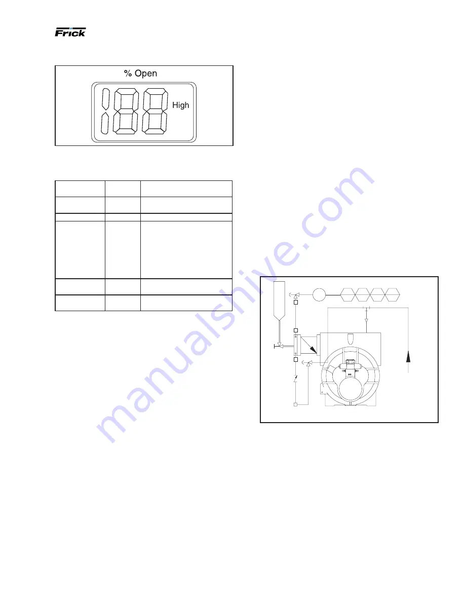
Figure 35: ICAD "high" function status
Alarms -
ICAD can handle and display different alarms.
Table 9: ICM alarms
Description
ICM alarm
text
Comments
No valve type
Selected
A1
At start-up
A1
and
CA
will be
displayed
Controller fault
A2
Internal fault inside electronics
All input error
A3
Not active if
i01
= 2 or
i02
= 2
When
i03
= 1 and AI A > 22 mA
When
i03
= 2 and AI A > 22 mA
Or Al A < 2 mA
When
i03
= 3 and AI A > 12 V
When
i03
= 4 and Al A > 12 V or
Al A < 1 V
Low voltage of
fail-safe supply
A4
If 5 VDC < Fail-safe supply
< 18 VDC
Check Supply
to ICAD
A5
If supply voltage < 18 VDC
If an alarm has been detected the ICAD display (see
) will alternate between showing actual alarm and pres
-
ent OD.
If more than one alarm is active at the same time, the
alarm with the highest priority will take preference.
A1
has
the highest priority,
A5
the lowest.
Any active alarm will activate the
Common Digital Alarm
output (Normally Open).
All alarms will automatically reset themselves when they
physically disappear.
Old alarms (alarms that have been active, but have physi
-
cally disappeared again) can be found in parameter
i11
.
Reset to factory setting:
1.
Remove the power supply.
2.
Activate down arrow and up arrow push buttons at the
same time.
3.
Connect the power supply.
4.
Release down arrow and up arrow push buttons.
5.
When the display on ICAD (see
) is alternating
between showing:
CA
and
A1
the factory resetting is
complete.
Suction check valve bypass
The RWF II unit is equipped with a low-pressure-drop
suction check valve bolted directly to the compressor
housing. Valve NV-2 must be open in most systems at all
times.
It should normally be cracked open to allow the
oil separator to slowly bleed down to approximately
system suction pressure when the unit is stopped
(hav
-
ing this valve cracked open allows the compressor drive
motor to have an easier start, and the
discharge check
valve will seat more tightly). If the drive coupling back
-
spins, start closing the valve until the backspin stops. If
the separator oil level foams excessively on shutdown,
NV-2 should be closed slightly. If the separator takes more
than 20 min to 30 min to equalize to suction pressure after
shutdown, NV-2 can be opened slightly. See
.
Check valve CV-4 is installed on all RWF II packages. On
high-stage systems, check valve CV-4 is installed with a
45 psi spring to avoid the possibility of back-feeding to a
shut-down compressor from a common economizer ves-
sel.
On booster systems, check valve CV-4 is installed with a
25 psi spring to avoid the possibility of air ingress into the
system, if the system suction pressure is below atmo-
spheric.
Figure 36: Suction check valve bypass
4
PE
PI
4
4
PIC
PAL
4
PALL
4
CV-4
SUCTION GAS
TO
THE COMPR
SC-14
SC-5
SE-1
COMPRESSOR END VIEW
NV-2
FROM
SEPARATOR
COLD-START
VALVE
Low ambient operation
It is recommended that oil separators be insulated as a
minimum requirement to preserve the heat generated by
the oil heaters. It is important that the coalescer end of
the separator be insulated to prevent refrigerant conden
-
sation.
On systems located outdoors or in unheated buildings
where the ambient temperature could drop below +40°F,
insulating and/or heat tracing of the compressor lube oil
systems is highly recommended.
When low ambient temperatures (below +20°F) are a pos
-
sibility, it is recommended that lube oil lines, oil filters, oil
pumps, and oil coolers be heat traced and insulated.
Freeze-up protection must also be provided for all water-
cooled equipment


