


QUANTUM™ LX/HD SYSTEM INTERFACE PANEL
INSTALLATION-OPERATION-MAINTENANCE
090.030-IOM (OCT 13)
Page 18
OPERATOR INTERFACE
DESCRIPTION
The Quantum™ SIP Operator Interface consists of two
components: A color 15” (diagonally measured) graphic
display and a resistive touchscreen and a membrane touch
overlay. The display is used to view information coming
from the Q5 controller, while the touchscreen allows the
operator to navigate the menus.
DISPLAY ASSEMBLY
The Display assembly consists of a 1024 x 768 resolution
LCD screen (which includes LED backlight sticks, and a
wiring harness). Refer to the Parts List at the end of this
manual for speci
fi
c replacement part numbers.
NOTE:
Before replacing a display unit, ensure that the
symptom is not actually being caused by a bad back-
light LED stick, harness or jumper setting.
DISPLAY REPLACEMENT
1. Shut off control power.
2. Carefully unplug the touchscreen connector
from the Q5 board. Ensure that you are familiar
with the relocation of this connector.
3. Remove the six nuts that mount the display plate
to the door.
4. Carefully lay the display plate down on a table or
bench, with the display side up.
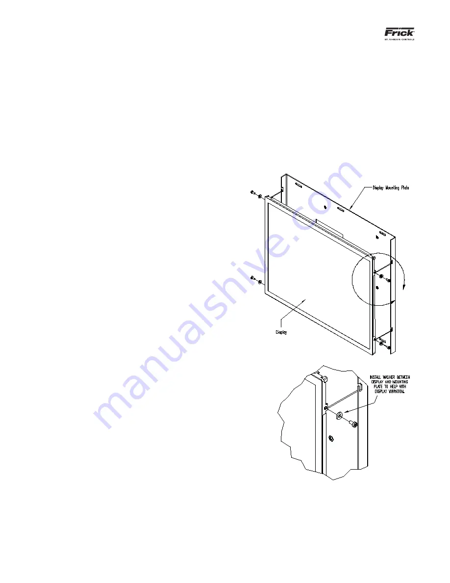
5. Loosen the four screws located on the display
plate as shown in detail A that follows.
6. Once all four screws have been loosened, care-
fully slide the display out of the slotted mounting
holes.
7. Remove the four screws and washers located at
the sides of the display.
8. Reinstall the new display by reversing steps 7
and 6, in that order. Use the tool marks left by
the hardware to position the new display.
9. Reinstall the display plate back into position on
the panel door, and loosely reinstall the six hex
nuts, do not tighten yet.
10. Carefully reconnect the display and backlight
connectors on the back of the display.
11. Look at the display from the front of the panel
door. Ensure that the display is centered in the
display opening. Once centered, tighten the six
nuts. Re-centering the display may be necessary
after these steps have been completed.
12. Verify the Q5 Motherboard Display jumper set-
tings per the table shown at on the previous
page.
A
DETAIL A


