Frick IDSC / ECOSS Series Скачать руководство пользователя страница 7

140.010-IOM (APR 2018)

Page 7

IDSC/ECOSS

 EVAPORATIVE CONDENSERS

INSTALLATION

INSTALLATION

TRANSPORTATION, STORAGE, 

UNPACKING AND MOUNTING


WARNING

Crushing danger with falling down! (see Appendix I, 4 

Transportation, Storage, Unpacking & Mounting)

TRANSPORTATION 

NOTICE

Read and observe all transport signs on the units' pack

-

aging! (see Appendix I, 4.1 Transportation)


STORAGE

NOTICE

Danger of corrosion and dirt build-up! (see Appendix 
I, 4.2 Storage)

See additional information in General Information section.

UNPACKING

The two parts of the unit are packed and shipped separately 
on their own substructure. See Figure 10.
After removing both sections of the unit from the truck: 

ü

  remove plastic wrapping

ü

  loosen bolts connecting the unit to the substructure

ü

  remove clamps, etc.

ü

  remove any accessories shipped loose in the basin (boxed)

ü

  ensure that delivery is complete and without damage. In 

case of damage or missing parts, contact the manufacturer 
immediately

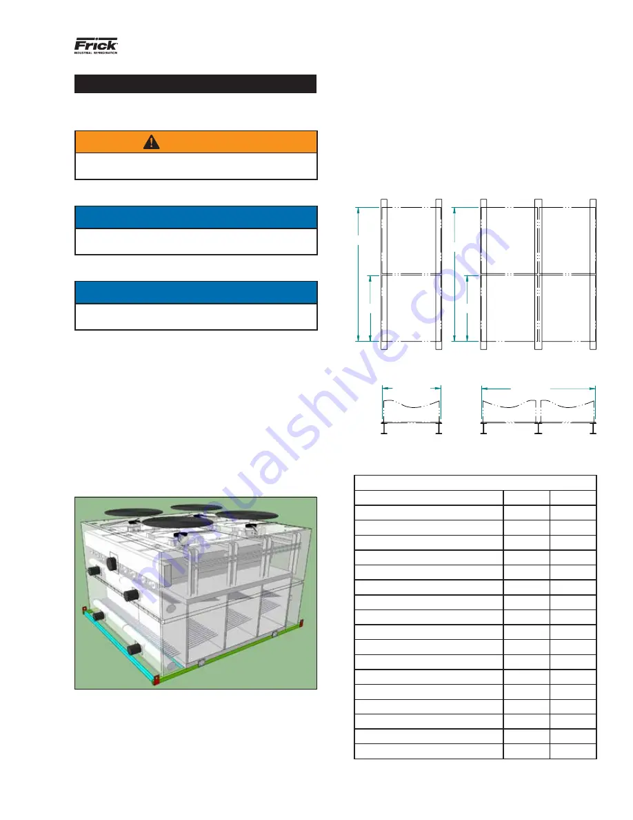
Figure 10 - Upper Section of Unit On Substructure

MOUNTING

Condensers will need to be structurally supported with two 
parallel I-beams traversing the entire length of the unit. 
(See Figure 11) I-beams must be level to within 1/8” over a 
6’ span. Shims cannot be used to level the unit as this will 
compromise the load bearing surface. 

Mounting holes (13/16” diameter) are provided at the base of 
the basin section, in the side panel flanges, to enable secur-
ing each unit to the support structure utilizing ¾” diameter 
bolts. Refer to the Frick unit certified drawing for the bolt 
hole locations.

All support beams and anchoring bolts will be provided 
by others and must be selected in accordance with sound 
structural engineering standards. When selecting the sup-
port beams, each beam should be calculated with a uniform 
load equivalent to 2/3 (66%) of the unit’s operating weight.

A1 & A2

A3 & A4

B3

B4

B2

B1


Figure 11 - IDSC/ECOSS

 Steel Support Dimensions (See 

Table for Dimensions)

IDSC/ECOSS

 Steel Support Dimensions

10' Wide Models

A1

B1

IDSC 1012-06-10 to -12-30

9' 9¾"

11' 11¾"

IDSC 1018-06-15 to -12-30

9' 9¾"

18' 4"

A2

B2

IDSC 1024-06-20 to -12-60

9' 9¾"

24' 1½"

IDSC 1036-06-20 to -12-80

9' 9¾"

36' 10"

12' Wide Models

A1

B1

IDSC 1212-08-15 to -12-40

11' 10"

11' 11¾"

IDSC 1218-08-20 to -12-50

11' 10"

18' 4"

A2

B2

IDSC 1224-08-30 to -12-80

11' 10"

24' 1½"

IDSC 1236-06-60 to -12-100

11' 10"

36' 10"

24' Wide Models

A3

B3

IDSC 2412-08-30 to -12-80

23' 10"

11' 11¾"

IDSC 2418-06-60 to -12-100

23' 10"

18' 4"

A4

B4

IDSC 2424-10-60 to -12-120

23' 10"

24' 1½"

IDSC 2436-08-80 to -12-200

23' 10"

36' 10"

Содержание IDSC / ECOSS Series

Страница 1: ...10 IOM OCT 2017 Dist 3 3a 3b 3c THIS MANUAL CONTAINS RIGGING ASSEMBLY START UP AND MAINTENANCE INSTRUCTIONS READ THOROUGHLY BEFORE BEGINNING INSTALLATION FAILURE TO FOLLOW THESE INSTRUCTIONS MAY RESUL...

Страница 2: ...Johnson Controls Frick makes no commitment to update or provide current information automatically to the manual owner that information if applicable can be obtained by contacting the nearest Frick Fac...

Страница 3: ...reatment Guidelines 16 TROUBLESHOOTING 17 SERVICE 17 TROUBLESHOOTING TABLE 17 APPENDIX I 1 GENERAL INFORMATION 18 1 1 RESPONSIBILITIES 18 1 2 LEGAL NOTES 18 1 3 OPERATING INSTRUCTIONS 19 1 3 1 Scope 1...

Страница 4: ...ty information please refer to Appendix I 2 Safety INFORMATION ON COMPONENT PARTS For safety information see Appendix I 3 Information on component parts CASING COIL BASIN WATER SYSTEM All Frick IDSC E...

Страница 5: ...r and over temperature protection real time diagnostics measured process value motor speed operating hours power consumption and motor temperatures lower EC motor temperature rise at reduced speed res...

Страница 6: ...sin at 40 F The design temperature of 40 F has been determined with the fans being off and options are available for ambient temperatures of 20 F Factory installed electrical contactors and wiring are...

Страница 7: ...I beams must be level to within 1 8 over a 6 span Shims cannot be used to level the unit as this will compromise the load bearing surface Mounting holes 13 16 diameter are provided at the base of the...

Страница 8: ...the support structure for bolt hole locations see unit certified drawing o Make sure that all mounting bolts are tightened equally to achieve a load distribution on the connections that is as balanced...

Страница 9: ...tions 10 WIDE UNITS 12 WIDE UNITS 18 LONG UNITS 12 LONG UNITS 60 120 0 10 48 106 3 8 10 3 138 2 11 6 2 120 0 10 113 9 9 5 9 51 109 0 9 1 120 0 10 120 0 10 49 Appropriately guiding the top section safe...

Страница 10: ...nger of damage to the system s cooling equipment see Appendix I 5 1 Safety instructions Damage to the system s cooling equipment NOTICE Danger of corrosion and dirt build up for units using ammonia as...

Страница 11: ...mes o Ensure that sufficient space is provided for mainte nance o Ensure that all liquid carrying components connection lines and all electrical connections and lines are easy to access o Ensure that...

Страница 12: ...connec tions the arrangement of the fittings and the ability to operate Check and retighten all threaded connections especially on the fans Check installation of pipe connections Check support of ref...

Страница 13: ...out with appropriate media and at the appropri ate test pressure Put the unit into operation see section 5 9 Putting the unit into operation for the first time PUTTING THE UNIT INTO OPERATION FOR THE...

Страница 14: ...ing and sanitizing the water distribution system sprinkler X X Basin cleaning and sanitizing X X Cleaning and sanitizing the side top and bottom panel enclosures fairings X X X Cleaning and sanitizing...

Страница 15: ...ng than under greasing If the bearing has a vent cap remove the cap and run pump for 30 minutes before reinstalling cap This allows excess grease to work its way out of the bearing Electrical motor Ch...

Страница 16: ...sfer products When dissolved solids become overly concentrated an adherent deposit termed scale will form on the tubes of the heat exchanger severely impacting the thermal performance of the heat exch...

Страница 17: ...aintenance schedule The water treatment program must be compatible with the unit s construction materials In systems with mixed metallurgy the water treatment expert must devise a program to ensure ad...

Страница 18: ...ational disrup tions a warning system which immediately signals all faults must be provided on site Prepare emergency measures that prevent consequential damage for people and property should faults o...

Страница 19: ...or otherwise injured with non com pliance Warns against hot surfaces The temperature is over 110 F protein clotting and can cause burns Warns against dangerous electrical voltage Danger of an electric...

Страница 20: ...g refrigerant liquid or vapor from the heat exchanger or pipe components o Sudden large release release and evaporation of the greater part of the entire refrigerant filling in a short time e g in les...

Страница 21: ...temperature Fan kW Air inlet bulb temperature The specified operating point is provided in the order related documents Operating Conditions The unit is a component of a cooling system including its re...

Страница 22: ...aces or clothing parts Do not operate fans without guard grille Pinch trap point hazard With automatic fan start during mainte nance work there is a danger of pinching trapping for the hands and finge...

Страница 23: ...ntrations Please ensure that the halocarbon refrigerant leaking from the unit cannot penetrate the interior of the building or put people at risk in any other way Halocarbon refrigerant vapor or gas m...

Страница 24: ...al Ensure that the maximum permissible limit values in the setup room are not exceeded Monitor the ammonia concentration in the ambient air with detectors and alarm devices Frostbite hazard Leaks in t...

Страница 25: ...ctrical components connections and cables no recognizable identifiers on the pipes and insufficient space for tests With ammonia units defective installation may also result in hazards caused by under...

Страница 26: ...il heat exchangers fans must be disposed of properly as specified Used refrigerant that is not determined for reuse must be treated as waste and safely disposed of There must be no emissions into the...

Страница 27: ...e unit is intended for outdoor use only To protect the unit from damage due to the elements the unit should be stored in a clean dry location and away from areas with excessive traffic The unit should...

Страница 28: ...d dirt may not get into the unit s in terior If humidity or dirt gets into the unit s interior fittings and other components of the refrigeration installation can be damaged Protect the unit against d...

Страница 29: ...not exercise any forces upon the distribution and header points This can cause leaks on the refrigerant connection points of the unit and on connection points of the on site pipe laying Ensure that R...

Страница 30: ...ICE For unit shutdown consider the maximum operating pressure If necessary take precautions so that it cannot be exceeded NOTICE With shutdown times of a month or longer energize the fans for approxim...

Страница 31: ...at can involve ignition sources ex grinding welding soldering etc With all work involving ignition sources ex grinding welding soldering etc in the work area keep suitable fire extinguishing equipment...

Страница 32: ...still under effervescence has a temperature of 28 F Contact with refrigerant under effervescence caused by spraying causes frostbite Use eye protection Use hand protection Ensure that the unit in ques...

Страница 33: ...this point in service life 6 6 CLEAN UNIT 6 6 1 General NOTICE If during maintenance or cleaning any corrosion is be ing detected please contact the manufacturer directly 6 6 2 Cleaning coil casing a...

Страница 34: ...ways be dependent on the loca tion wet bulb temperature and the heat load There are two methods to control the blow down bleed rate 1 Constant Blow Down manually setting the bleed regu lating valve at...

Страница 35: ...uate 13 Explosion hazard 24 eye protection 30 F fan blades 12 15 21 fan capacity 21 fan motor bearing 15 fan motor drives 13 fan motors 5 fans 25 Fans 27 fire extinguishing equipment 30 fittings 12 fl...

Страница 36: ...f device 27 system installer 17 T TEFC motor 6 terminal box 27 thermostat 6 threaded connections 12 U Unstable oils 27 V vaporous ammonia 23 variable motor speed 5 vent cap 15 ventilation system 11 vi...

Отзывы: