


140.010-IOM (APR 2018)
Page 16
IDSC/ECOSS
™
EVAPORATIVE CONDENSERS
MAINTENANCE
ü
Heavier moisture or greasy dirt must be removed with a
high-pressure water jet (max. 725 psi pressure), steam
pressure jet (max. 725 psig pressure), minimum 8 inches
away with a flat jet nozzle, or using a neutral cleaning
agent where applicable.
NOTE:
o With oily and greasy dirt it helps to add a cleaning
agent to the water.
o Cleaning should be done from inside to the outside
(always opposing the dirt onset) and from top to bot-
tom.
o Continue cleaning until all dirt has been removed.
WATER TREATMENT
WATER TREATMENT AND MINIMUM WATER
QUALITY REQUIREMENTS
Biological Control
With the inlet louvers structure of the side coverings, which
effectively shut out the sunlight and the double inclination
of the basin for complete drainage, it is ensured that there
will be minimal biological growth in the basin.
Chemical treatment
For necessary measures to maintain the prescribed limit
values (see Table "Recirculated Water Quality Guidelines),
please contact your local water treatment specialist.
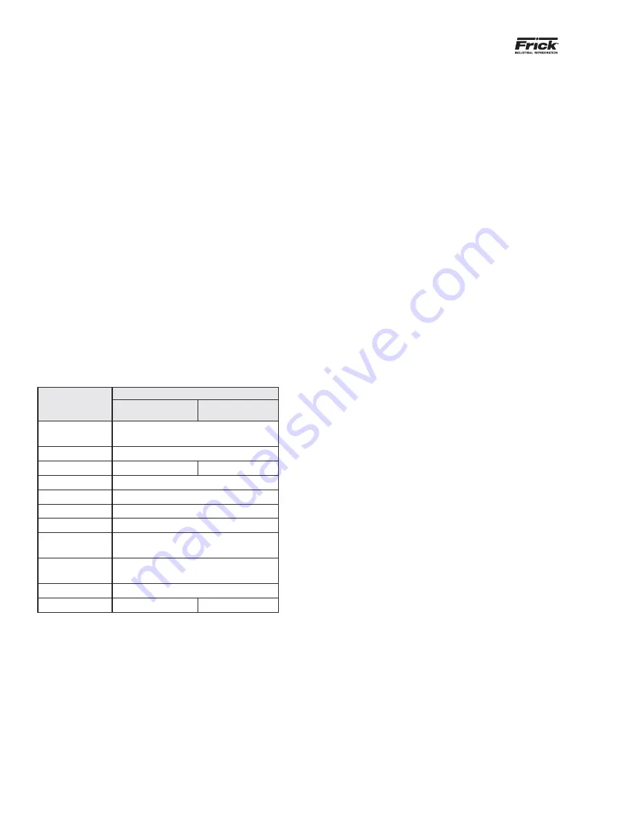
Recirculated Water Quality Guidelines
Property
Recommended Value
304L SST
316L SST
(Std. Tube Material)
Total Bacteria
(cfu/ml)
< 1,000
pH (90
°
F)
6.0 - 9.0
Chlorides as Cl
< 250 ppm
< 400 ppm
Sulfates as SO
4
2-
< 250 ppm
Silica
< 150 ppm
Hardness
< 500 ppm (as CaCO
3
)
Alkalinity
< 600 ppm (as CaCO
3
)
Total Dissolved
Solids
< 1,500 ppm
Total Suspended
Solids
< 40 ppm
Conductivity
< 3,000 (micromhos)
Free Chlorine
< 1.0 ppm
< 2.0 ppm
NOTES:
1. The water quality guidelines listed above are for clean
surfaces. Proper and periodic equipment maintenance is
required to prevent tube fouling, surface deposit(s), scale,
microbial deposit(s), etc. which in turn can reduce the range
of the guidelines provided above.
2. Water distribution nozzles are to be kept clean at all times
to ensure complete wetting of the coil. Failure to do so will
result in warranty being voided.
3. Only Non-Chlorinated Biocides should be used for biologi-
cal control.
4. Anaerobic dip slide: Sessile bacteria sampling must be
conducted along with bulk water (planktonic) sampling.
Water Treatment Guidelines:
Water related problems that typically occur in an evaporative
condenser can be broadly classified as:
•
Scale Deposits
• Corrosion
•
Microbiological Fouling
Scale deposits are a serious concern in evaporative heat
transfer products. When dissolved solids become overly
concentrated, an adherent deposit termed "scale" will form
on the tubes of the heat exchanger, severely impacting the
thermal performance of the heat exchanger. Evaporative
cooled deposits may also include dust scrubbed from the
air, corrosion byproducts and microbiological contaminants
(slime). Regardless of the source, the end result is reduced
thermal performance, increased operating costs and eventu-
ally, equipment failure.
Corrosion in water is usually an electrochemical reaction
initiated by the presence of naturally occurring impurities in
water or microbiological growth. Corrosion is the destructive
reaction of a metal with its immediate environment, resulting
in metal loss and ultimately equipment failure.
Metal corrosion occurs as a result of galvanic action at a
negatively charged pole, or site on the metal surface. Both
anodes and cathodes can be created on metal surfaces due
to impurities in the metal, localized stress, metal grain size
or composition differences. The difference in charges be-
tween anodes and cathodes creates an electrical potential
between them which results in an electrical charge flowing
from anodes to cathodes, using the surrounding water was
a conductor. General corrosion is wide spread and normally
caused by impurities in the metal or characteristics of the
metal or its environment that results in an overall fouling of
the metal surface. Localized corrosion results from stress or
localized environment.
Having a consistent maintenance program in place and
maintaining the equipment in a clean state all ascribe to the
longevity of IDSC/ECOSS units.
Microbiological fouling results from bacteria, fungi, zooplank-
ton and algae introduced into the system through makeup
water or filtered from the air. Fouling results when these
microorganisms grow in open systems rich in oxygen and
form slime on the surfaces of the equipment. Slime is an
aggregate of both biological and non-biological materials.
The best method of controlling biological fouling in evapora-
tive units is to keep them clean. At least twice during the
cooling season, the unit should be drained, scrubbed clean
and allowed to dry fully before refilling. Thereafter, a chemical
treatment will complete the process.
Uncontrolled microbiological fouling can cause major corro-
sion and deposit problems in evaporative units. Microbials in
condenser water systems can become resistant to a single
method of treatment, therefore it is recommended that both


