


Hardware Description
TWR-P1025 Hardware User Guide, Rev. 0
Freescale Semiconductor
9
Serial connectivity for both P1025 cores is provided through the mini type B USB connector (labeled mini
USB UART in
Figure 1-3
). Note that the USB Drivers should be installed onto the host PC before the serial
terminal can be used. These can be downloaded from;
http://www.ftdichip.com/Drivers/VCP.htm (FT2232)
A serial terminal can be set up using a PC communication program such as hyper terminal set to 115200
Baud, 8 data bits, no parity, 1 stop bit. You should select the first COM port assigned to the USB UART
Virtual COM port.
3.12
I2C
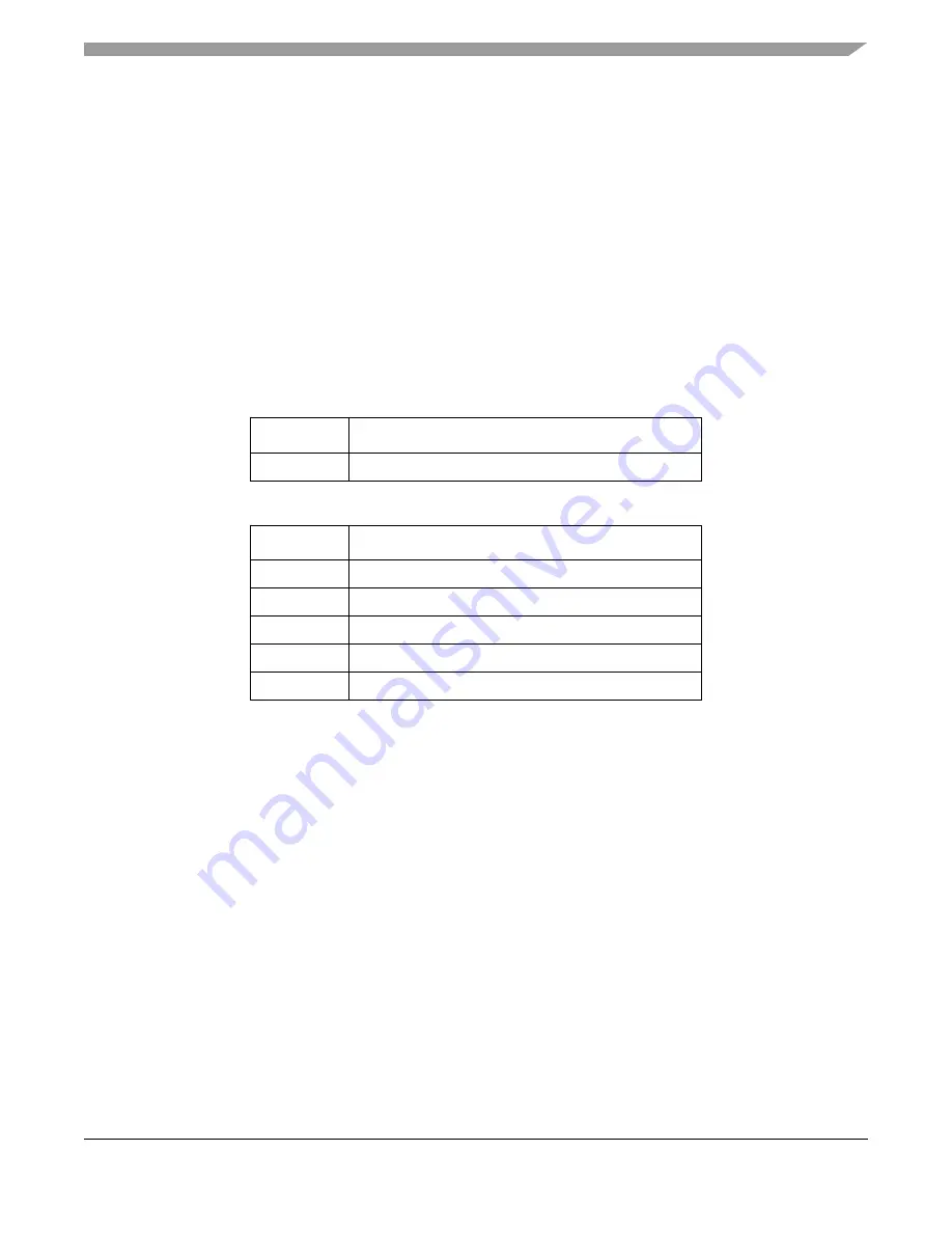
There are two I2C buses on the P1025, I2C1 and I2C2. I2C1 is intended for Boot Sequencer operation.
I2C2 is used for peripherals.
Table 3-7
&
Table 3-8
list the I2C devices attached to each bus.
3.13
SPI
The P1025 SPI is used to control the optional 50 MHz VXCO (DNP by default) and is also routed to the
tower primary elevator.
3.14
DDR3
512 MBytes of memory is connected to the P1025 32-bit DDR3 controller. The 512 MByte comprises of
two 128 Mbit x 32 bits x 8 banks (2-Gbit) devices (Micron MT41J128M16HA-125G).
The DDR3-SDRAM is configured with 14 row address lines, 10 column address lines, and 8 banks.
Control of each memory device is through the CS0 signal. Individual differential clocks and their
associated enable signal are routed to each memory.
Every DDR3 signal can be considered to be a member of one of four separate groups. Each group has
unique rules in terms of signal connection and signal routing. The four groups and connectivity between
controller and Memory are shown in
Table 3-9
.
Table 3-7. I2C1 Connectivity
Address
Device
0x50
M24256-BWDW6TP 2K EEPROM (16-bit address)
Table 3-8. I2C2 Connectivity
Address
Device
0x1C
MMA8451Q 3 Axis accelerometer
0x23
GPIO expander
0x52
AT24C01B 1K Board EEPROM (8-bit address)
TBD
Primary elevator
TBD
miniPCIe Slot